S3F84B8_UM_REV 1.00 22 DEVELOPMENT TOOLS
22-4
Table 22-1 TB84B8 Components
Mark Usage Description
S1 100-cable interface Connect the emulator and TB84B8
U4 20-cable interface Connect TB84B8 and user system
SW1 8- channel switch Smart Option configuration of S3E84B0
RESET Key Generate reset signal to S3E84B0
VCC, GND Power in Power supply for TB84B8
IDLE, STOP LED STOP/IDLE display Indicate S3E84B0 work status
JP5 Clock source selection Select clock source as from the emulator or board
JP7 Mode selection EVA /Main mode selection of S3E84B0
JP6 PWM selection Select whether PWM keeps output as the emulator pauses
JP4 User power selection Select user power supply
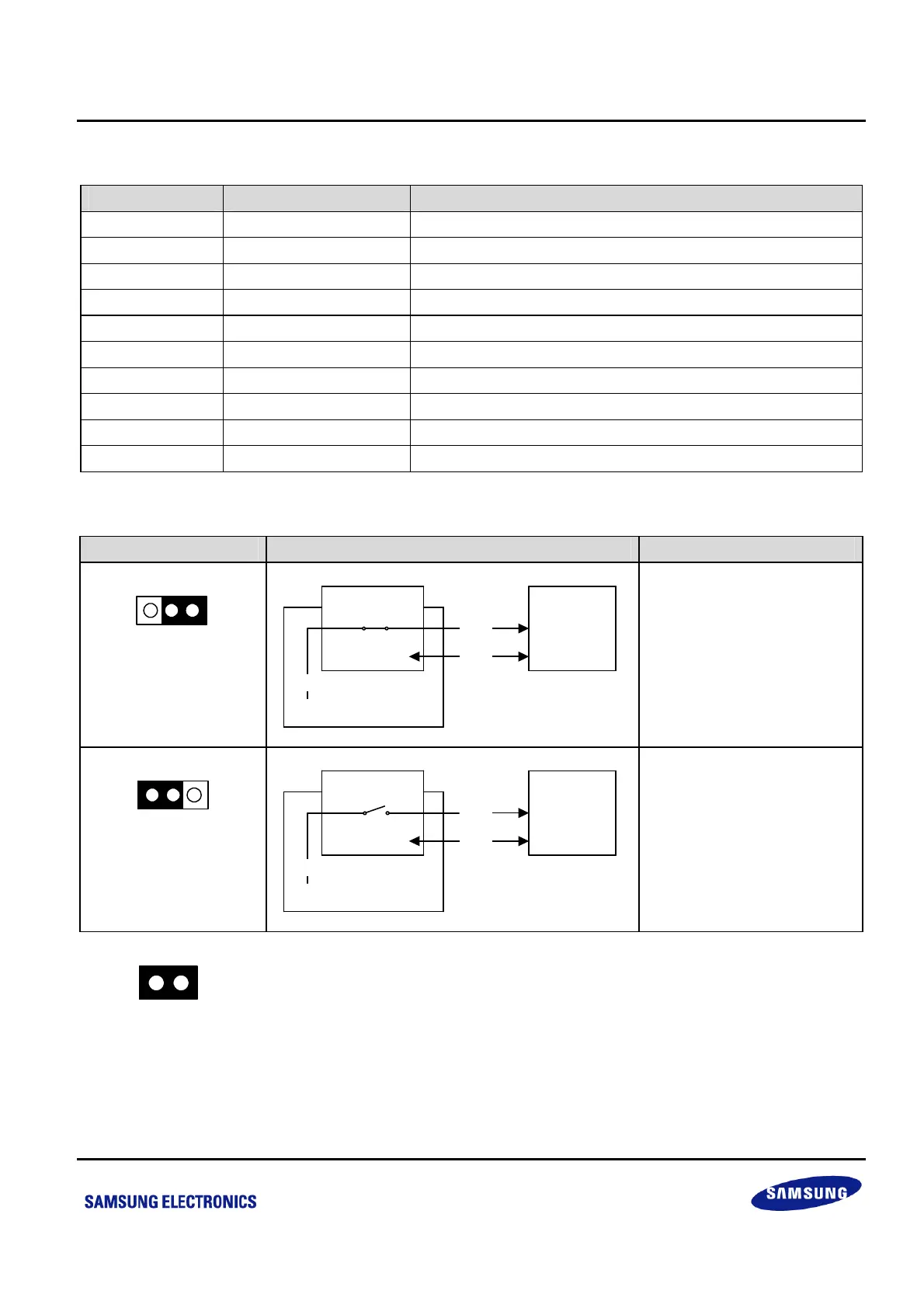
Table 22-2 Power Selection Settings for TB84B8
“To User_Vcc” Setting Operating Mode Comments
To user_Vcc
off
on
Target
System
SMDS2/SMDS2+
TB84B8
V
CC
V
SS
V
CC
External
The SMDS2/SMDS2+ main
board supplies V
CC
and Vss
to the target board
(evaluation chip) and target
system.
on
To user_Vcc
off
Target
System
SMDS2/SMDS2+
TB84B8
V
CC
V
SS
V
CC
External
The SMDS2/SMDS2+ main
board supplies V
CC
only to
the target board (evaluation
chip). The target system must
have its own power supply.
NOTE: The following symbol in the “To User_Vcc” Setting column indicates the electrical short (off) configuration:



 To Next Page