4.30
SEL-787 Relay Instruction Manual Date Code 20081022
Protection and Logic Functions
Basic Protection
Setting Calculation
Polarizing Quantity
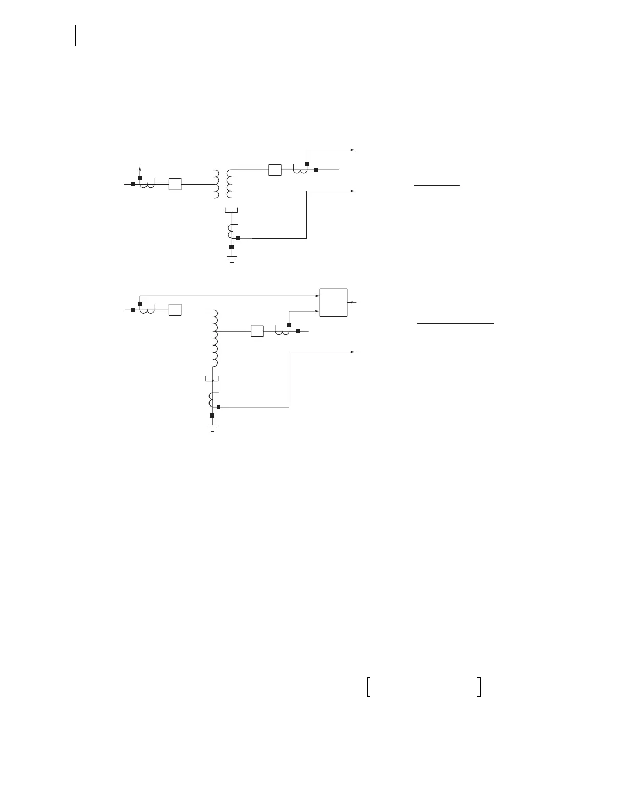
Figure 4.13 depicts how to determine the polarizing quantity, REF1POL,
setting.
Figure 4.13 REF Function, REF1POL Setting Guide
If you want to protect a single wye winding in, for example, a delta-wye
transformer, set REF1POL at 1 or 2, which is the number of the relay winding
input associated with the line-end CTs of the protected winding. The relay
uses residual current from that single winding input as the polarizing quantity.
If you want to protect an autotransformer, set REF1POL at 12 and connect the
primary and secondary side CTs to relay winding inputs 1 and 2. With
REF1POL set at 12, the relay sums the residual currents from the Winding 1
and Winding 2 inputs to create the polarizing quantity.
Calculation of the residual current at each relay winding input is as follows:
IGWn =IAWn + IBWn + ICWn (n =1, 2)
REF Current Pickup Level
The second criterion of 50REF1P relates to the relative sensitivity of the
winding CTs compared to the neutral CT. Use the following equation to
determine the minimum second criterion for 50REF1P:
where MAX(INOMn • CTRn) is the greatest primary rating of the CTs being
used for the REF function.
IPOL
IOP
Delta - Wye
W1
Neutral
W2
IPOL
IOP
Neutral
W2
REF1POL = 2
IPOL =
IOP = (IN1/INOMN1)
(IGW2•CTR2)
(CTRN1•INOM2)
REF1POL = 12
IPOL =
IOP = (IN1/INOMN1)
where INOMW = (INOM1+INOM2)/2
(IGW1•CTR1)+(IGW2•CTR2)
(CTRN1•INOMW)
Autotransformer
W1
Σ
50REF1P 0.05
MAX INOMn CTRn•()
CTRN1 INOMN1•()
-------------------------------------------------------------
•≥