5.4
SEL-787 Relay Instruction Manual Date Code 20081022
Metering and Monitoring
Metering
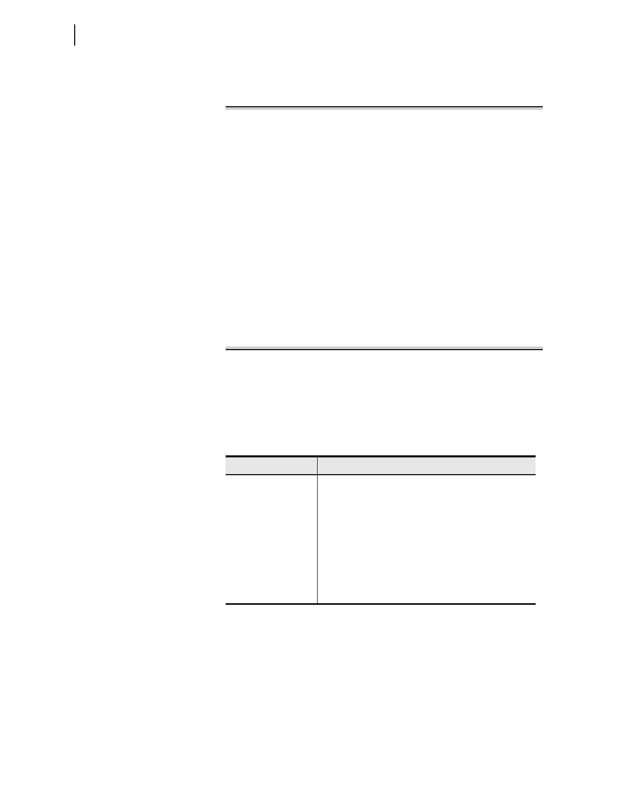
connected PT) or VAN < 13 V (for wye-connected PT), the angles are
referenced to IAW1 current. Figure 5.2 shows an example of the METER
command report.
=>>MET <Enter>
SEL-787 Date: 01/23/2008 Time: 13:46:49
TRNSFRMR RELAY Time Source: Internal
IAW1 IBW1 ICW1 IGW1 3I2W1 IAVW1
Wdg1 Mag (A pri.) 118.4 122.5 120.6 4.1 3.1 120.5
Wdg1 Angle (deg) -2.4 -122.3 117.9 -151.2 154.3 0.0
IAW2 IBW2 ICW2 IGW2 3I2W2 IAVW2
Wdg2 Mag (A pri.) 2357.6 2457.8 2402.2 97.3 76.8 2405.9
Wdg2 Angle (deg) -2.2 -122.3 118.0 -150.4 141.9 0.0
IN
Neutral Mag (A pri.) 147.0
Neutral Angle (deg) -1.0
VA VB VC VG 3V2 VAVE
Volt Mag (V pri.) 12094.5 12268.1 11894.3 1037.3 752.4 12085.6
Volt Angle (deg) 0.0 -120.0 124.0 -131.9 -5.6 0.0
Real Power (kW) 87032
Reactive Power (kVAR) 5360
Apparent Power (kVA) 87197
Power Factor (LAG) 1.00
Frequency (Hz) 60.0
V/Hz (%) 153.9
=>>
Figure 5.2 METER Command Report With Voltage Option
Differential Metering
The differential metering function in the SEL-787 reports the fundamental
frequency operate and restraint currents for each differential element (87) in
multiples of TAP. Table 5.2 shows the value reported. Figure 5.3 shows an
example of the METER DIF (differential) command report.
Table 5.2 Measured Differential Meter Values
Relay Option Differential Values
All Operate currents IOP1, IOP2, IOP3 in pu of TAP value for
elements 87-1, 87-2, and 87-3, respectively
Restraint currents IRT1, IRT2, IRT3 in pu of TAP value for
elements 87-1, 87-2, and 87-3, respectively
IOP1F2, IOP2F2, and IOP3F2 are 2nd harmonic currents as
a percentage of IOP1, IOP2, and IOP3, respectively.
IOP1F4, IOP2F4, IOP3F4 are 4th harmonic currents as a
percentage of IOP1, IOP2, and IOP3, respectively.
IOP1F5, IOP2F5, and IOP3F5 are 5th harmonic currents as a
percentage of IOP1, IOP2, and IOP3, respectively.