2.3
Date Code 20081022 Instruction Manual SEL-787 Relay
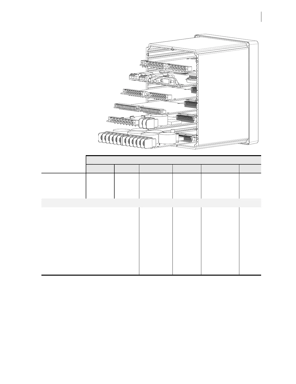
Installation
I/O Configuration
Figure 2.2 Slot Allocations for Different Cards
SELECT Power Supply With I/O (Slot A)
SEL
ECT Processor and
Communications Card (Slot B)
SEL
ECT I/O Expansion Card (Slot C)
SEL
ECT I/O Expansion Card (Slot D)
SEL
ECT I/O Expansion Card (Slot E)
SEL
ECT 6 ACI Card (Slot Z)
Rear-Panel Slot
A B C D E Z
Software Reference
1
(e.g., OUT101)
n/a 3
(e.g., IN301)
4
(e.g., OUT401)
5
(e.g., AI501)
n/a
Description
Power supply
and I/O card
a
a
Power supply, two inputs, and three outputs.
CPU/comm.
card
b
b
IRIG-B, EIA-232/485, fiber-optic serial and/or Ethernet ports
(The IRIG-B input option is available on terminals B01, B02 for models with Port 3 as an EIA-485 serial port. Models
with Port 3 as an EIA-232 serial port can input IRIG-B via the EIA-232 port and an SEL communications processor).
Comm. or input/
output
c
card
c
Digital or analog.
Input/output
c
or RTD card
Input/output
c
or
voltage/current card
CT card in
base unit
Card Type
SELECT EIA-232/485 z n/a n/a
SEL
ECT DeviceNet z n/a n/a
SEL
ECT 3 DI/4 DO/1 AO (one card per relay) zz z
SEL
ECT 4 DI/4 DO zz z
SEL
ECT 8 DI zz z
SEL
ECT 4 AI/4 AO (one card per relay) zz z
SEL
ECT 10 RTD n/a z n/a
SEL
ECT 1 ACI/3 AVI n/a n/a z
SEL
ECT 1 ACI n/a n/a z