4.71
Date Code 20081022 Instruction Manual SEL-787 Relay
Protection and Logic Functions
Trip/Close Logic
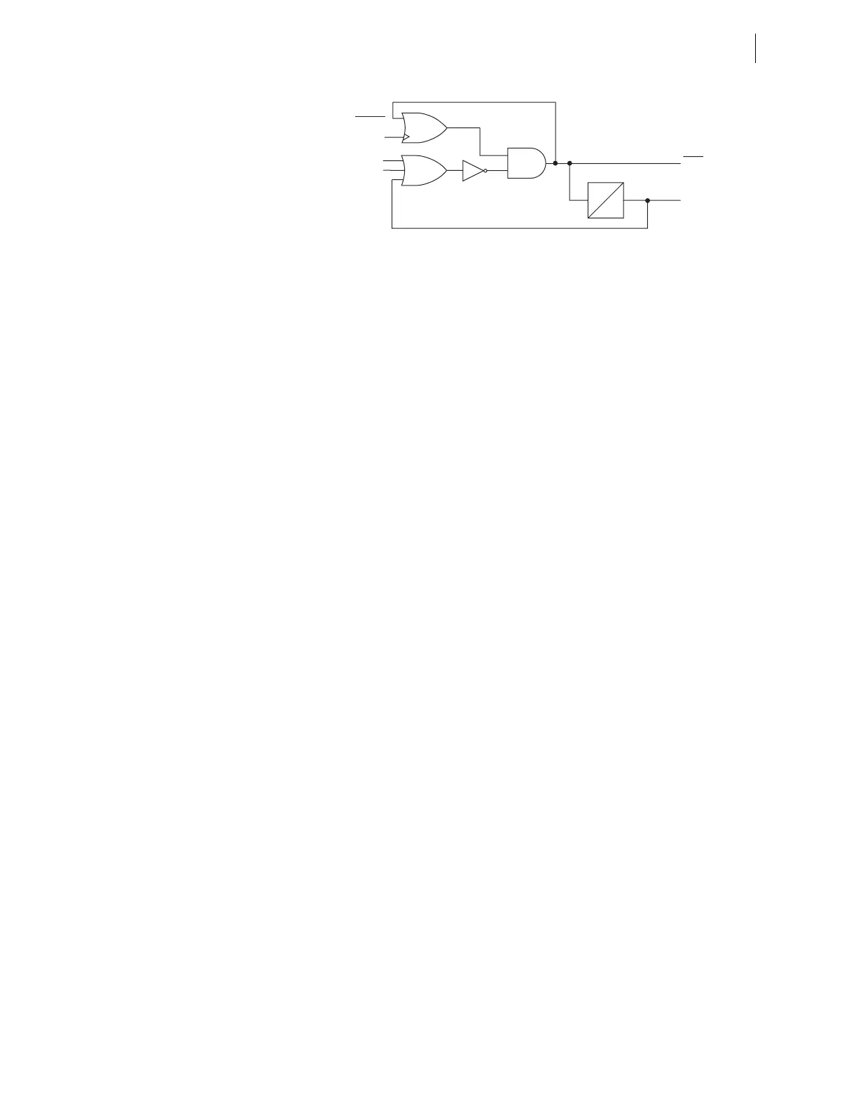
Figure 4.45 Close Logic
CL Close SELOGIC Control Equation
There are two close logic equations within the SEL-787. They are designed to
operate when
SELOGIC control equation close variable setting CLm is asserted
(m = 1, 2) and to unlatch when
SELOGIC control equation setting ULCLm is
asserted. The output of the logic is Relay Word bits CLOSEm.
The relay controls the closing output contact(s) when the Relay Word bit
CLOSEm appears in an output contact
SELOGIC control equation. Assign the
CLOSE bits to desired output relays as required by your application. See
Figure 2.19 for typical close circuit connection.
Set the CLm
SELOGIC control equations to include an OR-combination of all
Relay Word bits that you want to cause the associated close bits to assert. The
factory default setting already includes all commonly required Relay Word
bits.
Unlatch Close Logic
Each of the two close logic equations has an associated unlatch close SELOGIC
equation. Once a CLOSE bit is asserted it is sealed-in until all of the following
conditions are true:
➤ Unlatch Close SELOGIC control equation setting ULCL1 (or
ULCL2) asserts to logical 1.
➤ Relay Word 52A1 (or 52A2) asserts to logical 1.
➤ Close failure Relay Word bit asserts to logical 1.
Close Failure Logic
Each of the two close logic equations includes a close failure detection with an
associated delay setting (CFD1 and CFD2). Set the close failure delay equal to
the longest close time of the breaker plus a safety margin. If the breaker fails
to close, the Relay Word CF1 (or CF2) will assert for 1/4 cycle. Use the CF
bits as desired.
CFD1
0
CL1
ULCL1
CLOSE1
CF1
Close Failure Timer
SEL
OGIC
Equations
52A1
Relay
Word
Bits