Date Code 20081022 Instruction Manual SEL-787 Relay
Appendix J
Relay Word Bits
Instructi on Manual
Overview
The protection and control element results are represented by Relay Word bits
in the SEL-787 Transformer Protection Relay. Each Relay Word bit has a label
name and can be in either of the following states:
➤ 1 (logical 1)
➤ 0 (logical 0)
Logical 1 represents an element being picked up or otherwise asserted.
Logical 0 represents an element being dropped out or otherwise deasserted.
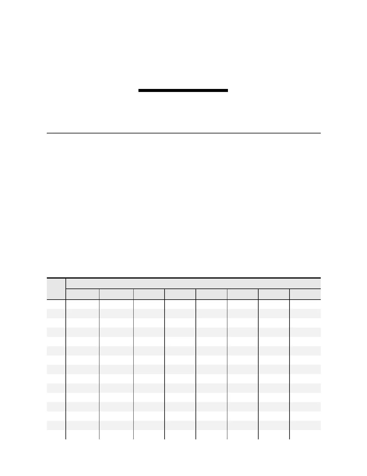
Table J.1 and Table J.2 show a list of Relay Word bits and corresponding
descriptions. The Relay Word bit row numbers correspond to the row numbers
used in the TAR command (see TARGET Command (Display Relay Word Bit
Status) on page 7.36).
Any Relay Word bit (except Row 0) can be used in
SELOGIC
®
control equations
(see Section 4: Protection and Logic Functions) and the Sequential Events
Recorder (SER) trigger list settings (see Section 9: Analyzing Events).
Ta b l e J.1 S E L- 787 Relay Word B i ts (Sheet 1 of 4)
Bit/
Row
Relay Word Bits
7 6 5 4 3 2 1 0
TAR 0
ENABLED TRIP_LED TLED_01 TLED_02 TLED_03 TLED_04 TLED_05 TLED_06
1
50P11T 50P12T 50P13T 50P14T 50P21T 50P22T 50P23T 50P24T
2
50G11T 50G12T 50Q11T 50Q12T 50G21T 50G22T 50Q21T 50Q22T
3
50N11T 50N12T 50NREF1 REF1E 50GREF1 REF1F REF1R REF1P
4
51P1T 51P2T 51G1T 51G2T 51Q1T 51Q2T 51N1T
a
5
87U1 87U2 87U3 87U 87R1 87R2 87R3 87R
6
TH5T 87AT 27P1T 27P2T 59P1T 59P2T 3PWR1T 3PWR2T
7
81D1T 81D2T 81D3T 81D4T BFT1 BFT2 59Q1T 59Q2T
8
24D1 24D1T 24C2 24C2T 24CR
aa
RTDT
9
REMTRIP
a a a a a
ORED50T ORED51T
10
50P11P 50P12P 50P13P 50P14P 50P21P 50P22P 50P23P 50P24P
11
50G11P 50G12P 50Q11P 50Q12P 50G21P 50G22P 50Q21P 50Q22P
12
50N11P 50N12P
aaaa
52A1 52A2
13
51P1P 51P2P 51G1P 51G2P 51Q1P 51Q2P 51N1P
a
14
51P1R 51P2R 51G1R 51G2R 51Q1R 51Q2R 51N1R
a