4.34
SEL-787 Relay Instruction Manual Date Code 20081022
Protection and Logic Functions
Basic Protection
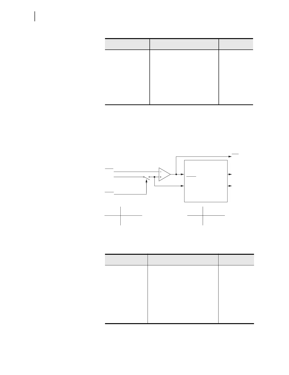
The maximum phase time-overcurrent elements, 51P1T and 51P2T, respond
to the highest of A, B, and C phase currents as shown Figure 4.15.
Figure 4.15 Maximum Phase Time-Overcurrent Elements 51P1T and 51P2T
Table 4.9 Winding n Maximum Phase Time-Overcurrent (n = 1 or 2)
Setting Prompt Setting Range
Setting Name :=
Facto ry Default
PHASE TOC LEVEL OFF, 0.50–16.00 A
a
,
0.10–3.20 A
b
a
For I
NOM
=5 A.
b
For I
NOM
=1 A.
51PnP := OFF
51PnP := OFF
PHASE TOC CURVE U1, U2, U3, U4, U5, C1, C2, C3, C4, C5 51PnC := U3
PHASE TOC TDIAL 0.50–15.00
c
,
0.05–1.00
d
c
For 5 1_ C := U_.
d
For 5 1_ C := C_ .
51PnTD := 3.00
EM RESET DELAY Y, N 51PnRS := N
CONST TIME ADDER 0.00–1.00 sec 51PnCT := 0.00
MIN RESPONSE TIM 0.00–1.00 sec 51PnMR := 0.00
PH TOC TRQCTRL SEL
OGIC 51PnTC := 1
Table 4.10 Residual Time-Overcurrent Settings (n = 1 or 2)
Setting Prompt Setting Range
Setting Name :=
Fa cto r y Defau lt
RES TOC LEVEL OFF, 0.50–16.00 A
a
,
0.10–3.20 A
b
a
For I
NOM
=5 A.
b
For I
NOM
=1 A.
51GnP := OFF
51GnP := OFF
RES TOC CURVE U1, U2, U3, U4, U5, C1, C2, C3, C4, C5 51GnC := U3
RES TOC TDIAL 0.50–15.00
c
,
0.05–1.00
d
c
For 5 1_ C := U_.
d
For 5 1_ C := C_ .
51GnTD := 1.50
EM RESET DELAY Y, N 51GnRS := N
CONST TIME ADDER 0.00–1.00 sec 51GnCT := 0.00
MIN RESPONSE TIM 0.00–1.00 sec 51GnMR := 0.00
RES TOC TRQCTRL SEL
OGIC 51GnTC := 1
51PnP
|IPWn|
Setting
51PnTC
Torque Control Switch
SEL
OGIC
Torque Control
Pickup
Curve
Timeout
Reset
51PnP
51PnR
51PnT
51PnTC Torque Control
State Switch Position
Logical 1 Closed
Logical 0 Open
Setting
51PnRS = Reset Timing
Y Electromechanical
N 1 Cycle
Relay
Word
Bits
SELOGIC
Setting
(From Figure 4.14)
Note: n = 1 or 2 (Winding 1 or 2).
51PnT Phase
Time-Overcurrent Element
Curve Timing and Reset Timing
51PnP Pickup
51PnC Curve Type
51PnTD Time Dial
51PnRS Electromechanical
Reset? (Y/N)
51PnCT Const. Time Add.
51PnMR Min. Response
Settings