4.18
SEL-787 Relay Instruction Manual Date Code 20081022
Protection and Logic Functions
Basic Protection
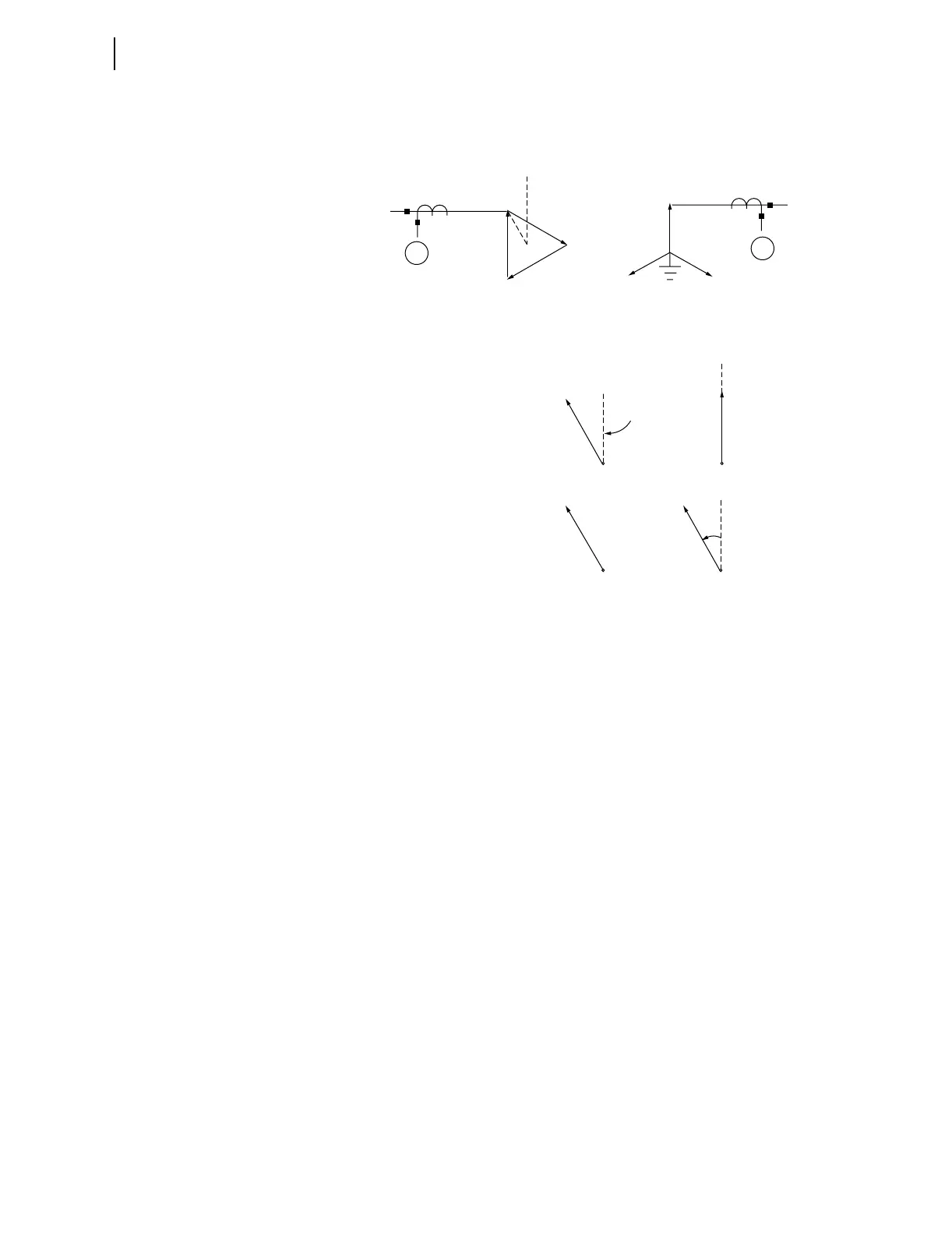
secondary winding whose direction is at “one o'clock” with respect to the
direction of the delta. The CT currents go to relay winding inputs 1 and 2 from
left to right as Figure 4.8 illustrates.
Figure 4.8 Example 1 for WnCTC Selection
The 115 kV delta primary and the 24.9 kV grounded-wye secondary represent
a traditional “DABY” two-winding application. This application has wye CTs
on the delta side and delta CTs on the wye side, using the same CT delta
connection as the primary of the transformer. Perform the following simple
steps to handle these traditional connections.
1. Establish the line terminal directions. Refer to the line
following the transformer drawings in Figure 4.8 and note that
the delta winding A line terminal direction is at 30 degrees
CCW from the A winding direction (vertical), as we would
expect for a DAB connection with ABC phase rotation. The A
winding of the 24.9 kV winding is vertical.
2. Adjust the CT connections. In this case the primary winding
with wye CTs need no adjustment. The 24.9 kV winding, with
DAB CTs, needs a 30-degree correction in the CCW direction.
Figure 4.8 shows this adjustment in the second line under the
transformer drawings.
3. Select a reference direction for the transformer. You can use
either one of the two winding directions as the reference, but
this need not be the case. You could establish any of the 12
possible directions, separated by 30 degrees around the
complete circle of 360 degrees, as the reference. Both windings
would then receive adjustments to correlate them with this
reference. As Figure 4.8 illustrates, the primary winding
direction serves as reference in the example.
Winding
A
Xfmr
Phase
Xfmr + CT
Phase
CTComp:
W1CTC = 0 W2CTC = 0
Terminal A
Vertical
Line
A
A
A
(REF.)
CT
Dy1 Connection (ABC Rotation)
115 kV
24.9 kV
A
(DAB)
C
B
Y
1
2
A
B
C
DAB