2.17
Date Code 20081022 Instruction Manual SEL-787 Relay
Installation
AC/DC Control Connection Diagrams
AC/DC Control Connection Diagrams
This section describes fail-safe versus nonfail-safe tripping, describes voltage
connections, and provides the ac and dc wiring diagrams.
Fail-Safe/Nonfail-Safe
Tripping
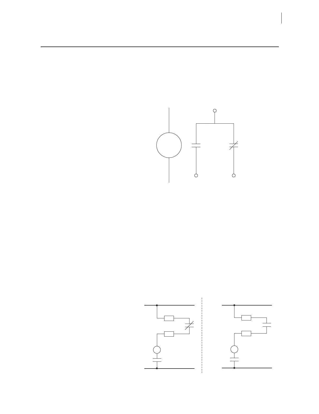
Figure 2.14 shows the output OUT103 relay coil and Form C contact. When the
relay coil is de-energized, the contact between A07 and A08 is open while the
contact between A07 and A09 is closed.
Figure 2.14 Output OUT103 Relay Output Contact Configuration
The SEL-787 provides fail-safe and nonfail-safe trip modes (setting
selectable) for all output contacts. The following occurs in fail-safe mode:
➤ The relay coil is energized continuously if the SEL-787 is
powered and operational.
➤ When the SEL-787 generates a trip signal, the relay coil is de-
energized.
➤ The relay coil is also de-energized if the SEL-787 power supply
voltage is removed or if the SEL-787 fails (self-test status is
FAIL).
Figure 2.15 shows fail-safe and nonfail-safe wiring methods to control
breakers.
Figure 2.15 OUT103 Contact Fail-Safe and Nonfail-Safe Options
A07
A08 A09
Contacts shown with
OUT103 relay coil de-energized
OUT103
Relay Coil
Nonfail-safe
OUT103FS = N
52A
Breaker Trip Coil
TC
A08
A07
A07
TC
52A
Fail-Safe
(Electrically Held)
OUT103FS = Y
Circuit Breaker
Breaker Trip Coil
A09