4.37
Date Code 20081022 Instruction Manual SEL-787 Relay
Protection and Logic Functions
Basic Protection
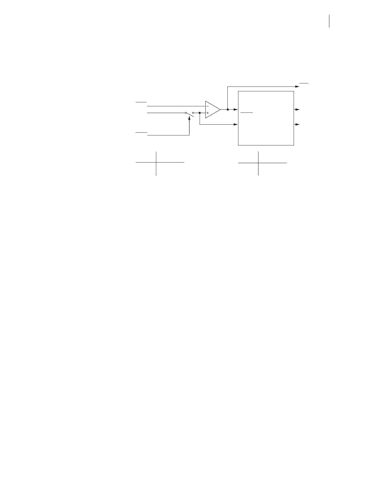
The neutral overcurrent and time-overcurrent elements, 50N11T, 50N12T, and
51N1T, respond to neutral channel current IN1 as shown Figure 4.14 and
Figure 4.18.
Figure 4.18 Neutral Time-Overcurrent Elements 51N1T and 51N2T
Relay Word Bit ORED51T
Relay Word bit ORED51T is asserted if any of the relay word bits 51P1T,
51P2T, 51G1T, 51G2T, 51Q1T, 51Q2T, OR 51N1T are asserted.
Time-Overcurrent Curves
The following information describes the curve timing for the curve and time
dial settings made for the time-overcurrent elements (see Table 4.14 and
Table 4.15). The time-overcurrent relay curves in Figure 4.19 through
Figure 4.28 conform to IEEE C37.112-1996 IEEE Standard Inverse-Time
Characteristic Equations for Overcurrent Relays.
51N1P
|IN1|
Setting
51N1TC
Torque Control Switch
SEL
OGIC
Torque Control
Pickup
Curve
Timeout
Reset
51N1P
51N1R
51N1T
51N1TC Torque Control
State Switch Position
Logical 1 Closed
Logical 0 Open
Setting
51N1RS = Reset Timing
Y Electromechanical
N 1 Cycle
Relay
Word
Bits
SELOGIC
Setting
(From Figure 4.14)
51N1T Neutral
Time-Overcurrent Element
Curve Timing and Reset Timing
51N1P Pickup
51N1C Curve Type
51N1TD Time Dial
51N1RS Electromechanical
Reset? (Y/N)
51N1CT Const. Time Add.
51N1MR Min. Response
Settings
t
p
= operating time in seconds
t
r
= electromechanical induction-disk emulation reset time in
seconds (if you select electromechanical reset setting)
TD = time-dial setting
M = applied multiples of pickup current [for operating time
(t
p
), M >1; for reset time (t
r
), M ≤ 1]