2.20
SEL-787 Relay Instruction Manual Date Code 20081022
Installation
AC/DC Control Connection Diagrams
Current Connections
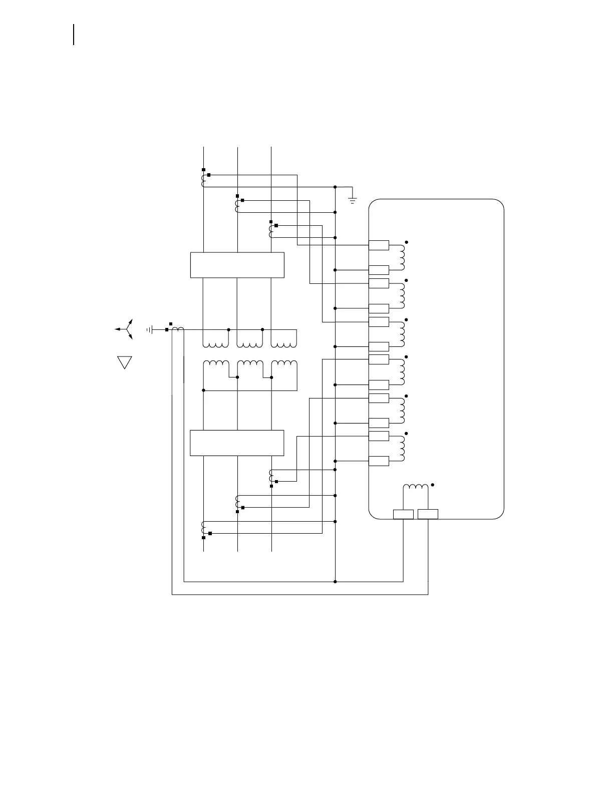
Figure 2.18 shows typical phase and neutral current connections for a
Transformer application. Figure 2.19 through Figure 2.22 show connection
diagrams for various applications. Wye-connected PTs are shown in
Figure 2.21; see Figure 2.16 and Figure 2.17 for other voltage connections.
Refer to Figure 2.23 for an example of dc connections for these applications
Figure 2.18 Typical Current Connections
Note 1. The IN input channel requires the optional single current channel 1 ACI current card in Slot E.
2. The CT secondary circuit must be grounded in the relay cabinet.
IAW1
IBW1
ICW1
IAW2
IBW2
ICW2
SEL-787 Relay
52-1
52-2
A B C
a b c
IN
Z01
Z02
Z03
Z04
Z05
Z06
Z07
Z08
Z09
Z10
Z11
Z12
E10
E09
(Optional Neutral
CT Input)
A
B
C
a
b
c