4.85
Date Code 20081022 Instruction Manual SEL-787 Relay
Protection and Logic Functions
Global Settings (SET G Command)
Changing the BFI and/or 52ABF settings can modify the default breaker
failure logic.
➤ Set BFI1 = R_TRIG TRIP1 OR R_TRIG TRIPXFMR AND
NOT IN102 if input IN102 is manual trip only and breaker
failure initiation is not desired when the tripping is caused by
this input.
➤ Set 52ABF = Y if you want the breaker failure logic to detect
failure of breaker/contactor auxiliary contact to operate during
the trip operation as defined by the BFI setting.
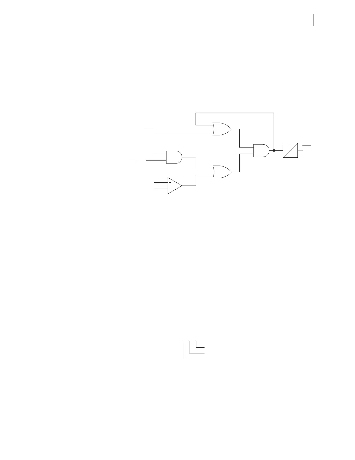
Figure 4.54 Breaker Failure Logic
Through-Fault
Monitoring
The power transformers are subjected to heavy through currents for the system
faults outside the transformer protection zone. The SEL-787 provides
monitoring of the Through-Fault current. See Section 5: Metering and
Monitoring for description and Table 5.10 for the settings.
Analog Inputs
The SEL-787 samples the analog inputs four times per cycle. For analog
inputs, set the following parameters for each input:
➤ Analog type
➤ High and low input levels
➤ Engineering units
Because of the flexibility to install different cards in the rear-panel slots on the
device, the setting prompt adapts to the x and y variables shown in
Figure 4.55. Variable x displays the slot position (3 through 5), and variable y
displays the transducer (analog) input number (1 through 4).
Figure 4.55 Analog Input Card Adaptive Name
Analog Input Calibration Process
In the analog input circuit, the dominant error is signal offset. To minimize the
signal offset, we adjust each of the device analog input channels by a
compensation factor. These compensation factors correct the signal offset
errors to within ±1 µA or ±1 mV.
52ABF = Y
BFIn
Setting
52An
0.02 • I
NOM
n
|I1Wn| + |I2Wn|
BFDn
0
Relay
Word
Bit
BFTn
Relay
Word
Bit
n = 1, 2 for breaker 52-1, 52-2, res
ectively
Inputs Number (1 through 4)
Slot Position (3 through 5)
Analo
In
ut
Ix0y