2.13
Date Code 20081022 Instruction Manual SEL-787 Relay
Installation
Rear-Panel Connections
Rear-Panel Connections
Rear-Panel and Side-
Panel Diagrams
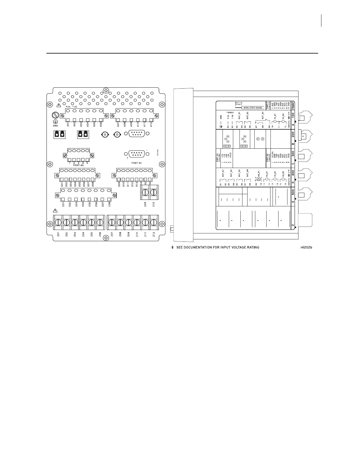
The physical layout of the connectors on the rear-panel and side-panel
diagrams of three sample configurations of the SEL-787 are shown in
Figure 2.9, Figure 2.10, and Figure 2.11.
Figure 2.9 Dual-Fiber, Ethernet, EIA-232 Communication, 3 DI/4 DO/1 AO, and Current/Voltage (1 ACI/3 AVI)
Option
i4201a
PORT 2
TX RX
1
9
PORT 3
PORT 1A PORT 1B
ACI
A
VI
E10
IN
E09
WYE
OPEN
DELT
A
E05
E06
N/C
N/
CE08
E07
N/C
N/
C
E02 VB
VB
(C
OM)
E03 VC V
C
E04 N C
OM
VA VAE01
+5 Vdc
RXD
+I RIG–B
TXD
GND5
–I RIG–B
RTS
GND
PORT 3
EIA–23
2
PORT 2
FI BER OPT I C
TX
R
X
1
2
4
3
6
8
CTS
7
9
PORT 1B
ETHERNET
100BASE–FX
FI BER OPT I
C
PORT 1A
ETHERNET
100BASE–FX
FI BER OPT I
C
Z02
IA
W1
Z03
Z04
IB
W1
Z05
Z06
IC
W1
Z01
Z08
IA
W2
Z09
Z10
IB
W2
Z11
Z12
IC
W2
Z07
(A) Rear-Panel Layout
(B) Side-Panel Input and Output Designations