2.10
SEL-787 Relay Instruction Manual Date Code 20081022
Installation
I/O Configuration
Analog Output (4 AI/
4AO Card) Voltage/
Current Jumper
Selection
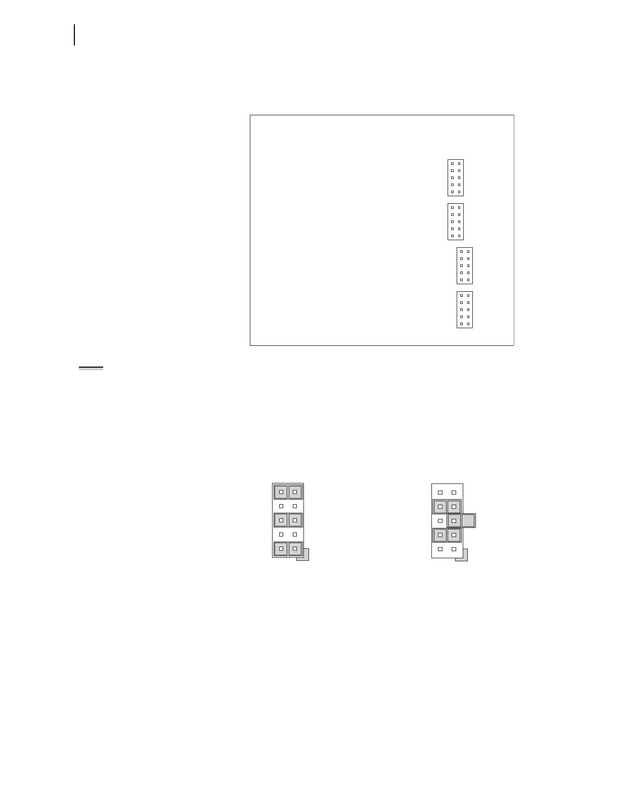
Figure 2.4 shows the locations of JMP1 through JMP4 on an Analog Output
board. You can select each of the four analog output channels as either a
current analog output or a voltage analog output.
Figure 2.4 JMP1 Through JMP4 Locations on 4 AI/4 AO Board
NOTE:
There is no jumper between
pins 5 and 6 for a voltage analog
output selection.
You need to insert three jumpers for a current analog output selection and two
jumpers for a voltage analog output selection. For a current analog output
selection, insert a jumper between pins 1 and 2, pins 5 and 6, and pins 9 and
10. For a voltage analog output selection, insert a jumper between pins 3 and
4, and pins 7 and 8. Figure 2.5 shows JMP4 selected as a current analog
output. The current analog output selection is the default setting for JMP1
through JMP4. Figure 2.6 shows JMP1 selected as a voltage analog output.
9
7
5
3
1
10
8
6
4
2
JMP1
9
7
5
3
1
10
8
6
4
2
JMP2
9
7
5
3
1
10
8
6
4
2
JMP3
9
7
5
3
1
10
8
6
4
2
JMP4
Figure 2.5 Current Output Jumpers Figure 2.6 Voltage Output Jumpers
9
5
1
10
6
2
JMP4
JMP4 Selected as Current Output
7
5
3
8
6
4
JMP1
JMP1 Selected as Voltage Output