7.5
Date Code 20081022 Instruction Manual SEL-787 Relay
Communications
Communications Interfaces
Table 7.2 shows the pin functions for the EIA-232 and EIA-485 serial ports.
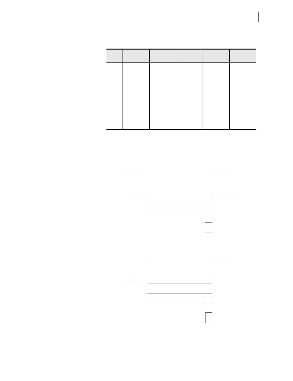
The following cable diagrams show several types of EIA-232 serial
communications cables that connect the SEL-787 to other devices. These and
other cables are available from SEL. Contact the factory for more information.
Figure 7.2 SEL Cable C234A—SEL-787 to DTE Device
Figure 7.3 SEL Cable C227A—SEL-787 to DTE Device
Table 7.2 EIA-232/EIA-485 Serial Port Pin Functions
Pin
a
a
For EIA-485, the pin numbers represent relay terminals _O1 through _05.
PORT 3
EIA-232
PORT 3
EIA-485
a
PORT 4C
EIA-232
PORT 4A
EIA-485
a
PORT F
EIA-232
1 +5 Vdc +TX +5 Vdc +TX N/C
2 RXD –TX RXD –TX RXD
3 TXD +RX TXD +RX TXD
4IRIG+
b
b
See Models, Options, and Accessories on page 1.2 for availability of IRIG-B.
–RX N/C –RX N/C
5 GND Shield GND Shield GND
6IRIG–
b
N/C N/C
7 RTS RTS RTS
8 CTS CTS CTS
9 GND GND GND
SEL-787 Relay
9-Pin Male
D Subconnector
9-Pin Female
D Subconnector
2
3
5
8
3
2
5
8
7
1
4
6
RXD
TXD
GND
CTS
TXD
RXD
GND
CTS
RTS
DCD
DTR
DSR
Pin
Func.
Pin
Func.
Pin # Pin #
*DTE Device
*DTE = Data Terminal Equipment (Computer, Terminal, etc.)
SEL-787 Relay
9-Pin Male
D Subconnector
25-Pin Female
D Subconnector
5
3
2
9
8
7
3
2
1
4
5
6
8
20
GND
TXD
RXD
GND
CTS
GND
RXD
TXD
GND
RTS
CTS
DSR
DCD
DTR
Pin
Func.
Pin
Func.
Pin # Pin #
*DTE Device
*DTE = Data Terminal E
ui
ment (Com
uter, Terminal, etc.)