2.12
SEL-787 Relay Instruction Manual Date Code 20081022
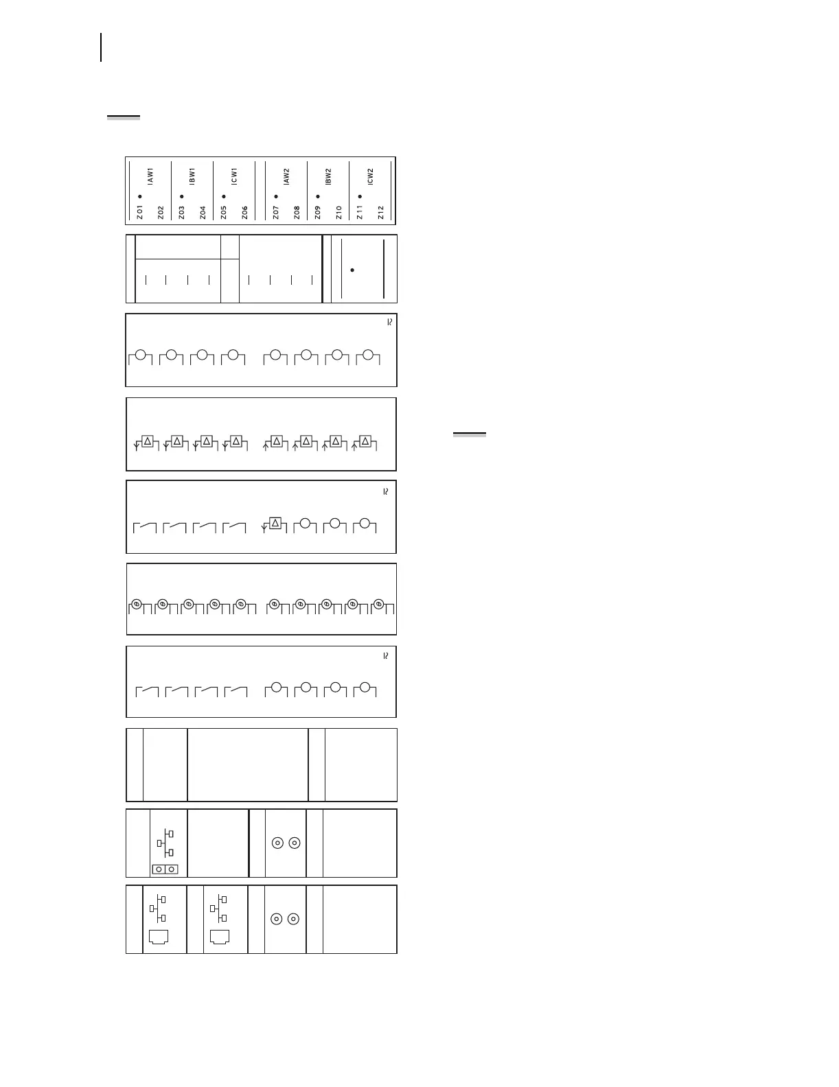
Installation
I/O Configuration
Rear-Panel Connections
Figure 2.8 shows the rear-panel connections for selected cards. Connections
for additional cards are shown in Figure 2.9 through Figure 2.11.
Figure 2.8 Rear-Panel Connections of Selected Cards
NOTE: After any change, be sure to
thoroughly test the settings.
AO_02
AO_0 1
AO_03
AO_04
AI_02
AI_01
AI_03
AI_04
08
05
06
02
04
09
03
10
11
12
13
14
15
16
07
01
INPUTS:
AO_0 1
IN_01
IN_02
IN_03
OUT_0 1
OUT_02
OUT_03
OUT_04
08
05
06
02
04
09
03
10
11
12
13
14
15
16
07
01
+
—
INPUTS:
IN_01
IN_02
IN_03
IN_04
OUT_0 1
OUT_02
OUT_03
OUT_04
08
05
06
02
04
09
03
10
11
12
13
14
15
16
07
01
08
05
06
04
09
20
21
22
23
24
25
26
27
28
29
30
10
11
12
13
14
15
16
17
18
19
07
02
03
01
RTD 1
COMP/ SHLD
+
—
RTD2
COMP/ SHLD
+
—
RTD3
COMP/ SHLD
+
—
RTD4
COMP/ SHLD
+
—
RTD5
COMP/ SHLD
+
—
RTD6
COMP/ SHLD
+
—
RTD7
COMP/ SHLD
+
—
RTD8
COMP/ SHLD
+
—
RTD9
COMP/ SHLD
+
—
RTD 1 0
COMP/ SHLD
+
—
PORT 4C
+5 Vdc
RXD
N/C
TXD
GND
5
N/C
RTS
GND
E IA–232
1
2
4
3
6
8
CTS
7
9
+TX
–TX
+RX
–RX
SHLD
5
PORT 4A
EIA–485
1
2
4
3
+5 Vdc
RXD
+IRIG–B
TXD
GND5
–IRIG–B
RTS
GND
PORT 3
EIA–23
2
PORT 2
FIBER OPTI C
TX
R
X
1
2
4
3
6
8
CTS
7
9
PORT 1
ETHERNET
100BASE–FX
FIBER OPTI
C
+5 Vdc
RXD
+IRIG–B
TXD
GND
5
–IRIG–B
RTS
GND
PORT 3
EIA–23
2
PORT 2
FIBER OPTIC
TX
R
X
1
2
4
3
6
8
CTS
7
9
PORT 1B
ETHERNET
10/100BASE–
T
PORT 1A
ETHERNET
10/100BASE–
T
ACI
A
VI
E10
IN
E09
WYE
OPEN
DELT
A
E05
E06
N/C
N/
CE08
E07
N/C
N/
C
E02 VB
VB
(C
OM)
E03 VC V
C
E04 N C
OM
VA VA
E01
INPUTS:
08
05
06
02
04
09
03
10
11
12
13
14
15
16
07
01
IN_0 1
IN_02
IN_03
IN_04
IN_05
IN_06
IN_07
IN_08
Card 1: Current Card With Six CT Inputs (6 ACI)
Card 2: Card With Three PT And 1 CT Inputs (1 ACI/3 AVI)
Card 3: Eight Digital Input Card (8 DI)
Card 4: Four Analog Input/Four Analog Output Card (4 AI/4 AO)
NOTE: Analog outputs are isolated from each other
and from the chassis ground.
Card 5: Three Digital Input/Four Digital Output/One Analog
Output Card (3 DI/4 DO/1 AO)
Card 6: RTD Card (10 RTD)
Card 7: Four Digital Input/Four Digital Output Card (4 DI/4 DO)
Card 8: Communications Card (EIA-232/EIA-485)
Card 9: Main Board With Single Fiber-Optic Ethernet, Fiber-
Optic Serial, and EIA-232 Rear Ports
Card 10: Main Board With Dual Copper Ethernet, Fiber-Optic
Serial, and EIA-232 Rear Ports