4.6
SEL-787 Relay Instruction Manual Date Code 20081022
Protection and Logic Functions
Basic Protection
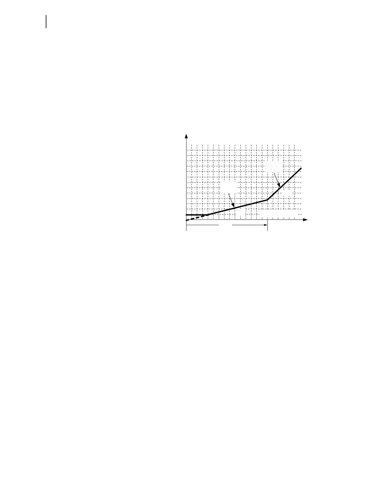
The four settings that define the characteristic are:
O87P = minimum IOP level required for operation
SLP1 = initial slope, beginning at the origin and intersecting O87P at
IRT = O87P • 100/SLP1
IRS1 = limit of IRT for SLP1 operation; intersection where SLP2 begins
SLP2 = second slope must be greater than or equal to SLP1
By careful selection of these settings, the user can duplicate closely the
characteristics of existing differential relays that have been in use for many
years.
Figure 4.1 Percentage Restraint Differential Characteristic
Figure 4.2, Figure 4.3, and Figure 4.4 illustrate how input currents are
acquired and used in the unrestrained and restrained differential elements.
Data acquisition, filtering, tap scaling, and transformer and CT connection
compensation for Winding 1 are shown in Figure 4.2.
Four digital filters extract the fundamental, second, fourth, and fifth (not
shown) harmonics of the input currents.
Using the transformer MVA rating as a common reference point, TAP scaling
converts all secondary currents entering the relay from the two windings to per
unit values, thus changing the ampere values into dimensionless multiples of
TAP. Throughout the text, the term “TAP” refers to the per-unit value common
to both windings, whereas “TAPn” refers to the ampere value of a particular
winding(s); TAPmin and TAPmax refer to the least and greatest of the two
TAP n values. This method ensures that, for full-load through-current
conditions, all incoming current multiples of tap sum to 1.0 and all outgoing
current multiples of tap sum to –1.0, with a reference direction into the
transformer windings.
Transformer and CT connection compensation adjusts the sets of three-phase
currents for the phase angle and phase interaction effects introduced by the
winding connection of the transformer and CTs. Settings W1CTC and
W2CTC determine the mathematical corrections to the three-phase currents
for Winding 1 and Winding 2, respectively. CTC1 is shown in Figure 4.2 as
the phase angle and sequence quantity adjustment for Winding 1.
I1W1C1, I2W1C1, and I3W1C1 are the fundamental frequency A-phase,
B-phase, and C-phase compensated currents for Winding 1. Similarly,
I1W1C2, I2W1C2, and I3W1C2 are the second-harmonic compensated
Operating Region
Restraining Region
IRT
60%
25%
IOP
087P = 0.3
Slope 2
(SLP2)
IRS1 = 3
Slope 1
(SLP1)