8.12
SEL-787 Relay Instruction Manual Date Code 20081022
Front-Panel Operations
Operation and Target LEDs
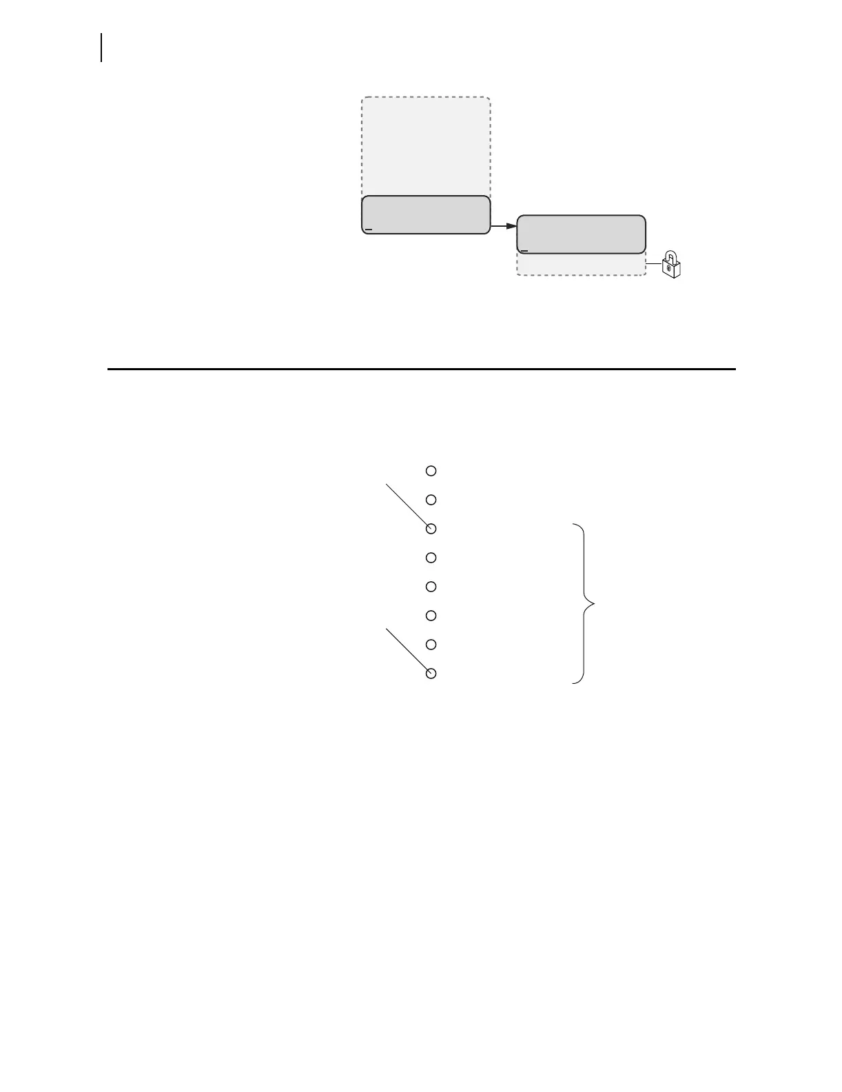
Figure 8.22 MAIN Menu and Status Submenu
Operation and Target LEDs
Programmable LEDs
The SEL-787 provides quick confirmation of relay conditions via operation
and target LEDs. Figure 8.23 shows this region with factory default text on the
front-panel configurable labels. See Target LED Settings on page 4.105 for the
SEL
OGIC control equations.
Figure 8.23 Factory Default Front-Panel LEDs
You can reprogram all of these indicators except the ENABLED and TRIP LEDs
to reflect operating conditions other than the factory-default programming
described in this subsection.
Settings T0n_LED are SEL
OGIC control equations that, when asserted during
a relay trip event, illuminate the corresponding LED. Parameter n is a number
from 1 through 6 that indicates each LED. The target LEDs can be set to latch
by the user. The setting T0nLEDL is set to Y to accomplish this. This setting
is set to N to disable the latch. After setting the target LEDs, issue the TAR R
command to reset the target LEDs. For a concise listing of the default
programming on the front-panel LEDs, see Table 4.57.
The SEL-787 comes with blank slide-in labels for custom LED designations
that match custom LED logic. The Configurable Label kit (includes blank
labels, word processor templates, and instructions) is shipped with the
SEL-787.
MAIN
Meter
Events
Targets
Control
Set/Show
Status
(Status Selected)
STATUS
Relay Status
Reboot Relay
T01_LED
Factory Default Label
T06_LED
ENABLED
TRIP
DIFFERENTIAL
INST. OVERCURRENT
TIME OVERCURRENT
OVER/UNDER VOLTAGE
OVER/UNDER FREQUENCY
VOLTS/HERTZ