2.25
Date Code 20081022 Instruction Manual SEL-787 Relay
Installation
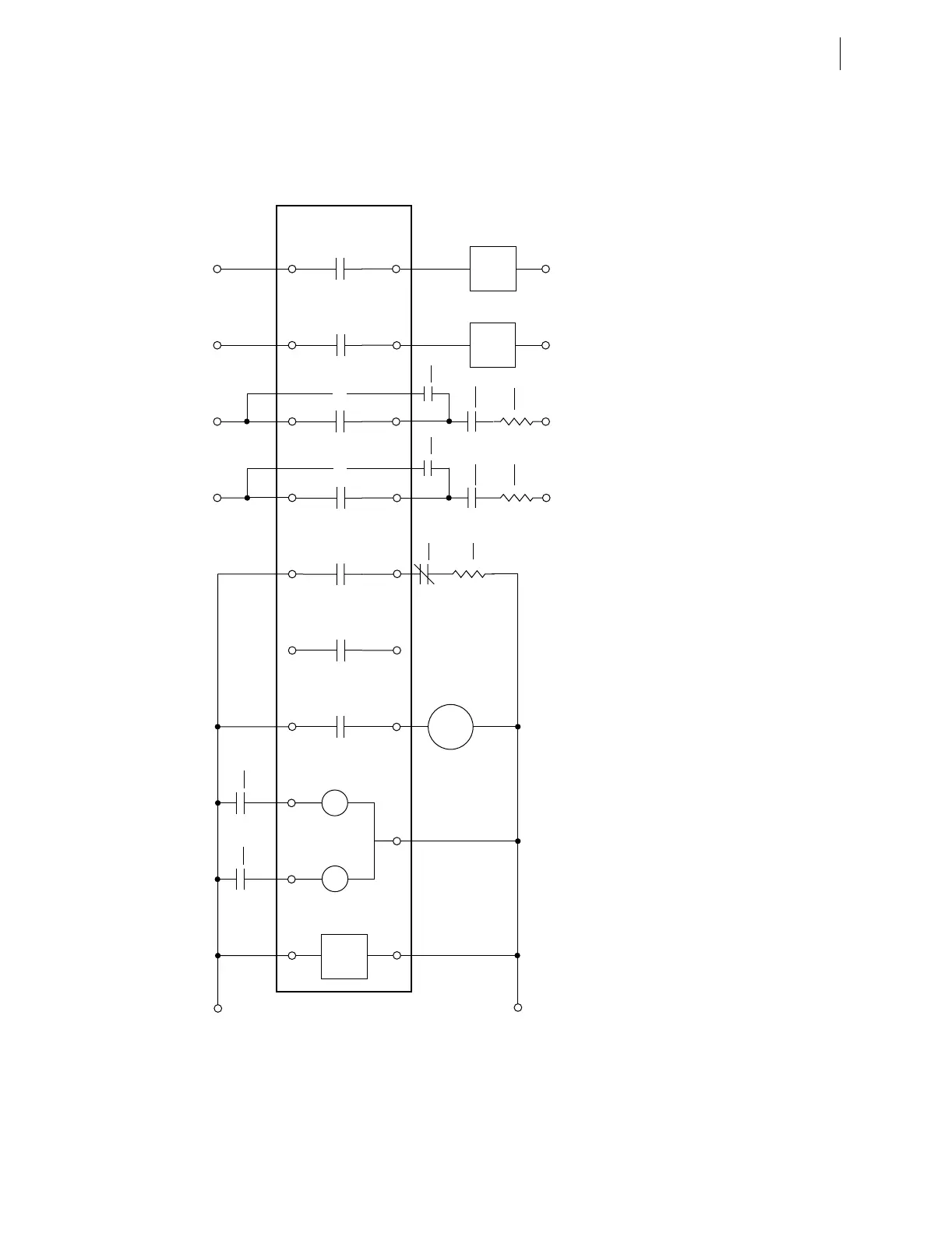
AC/DC Control Connection Diagrams
Figure 2.23 Example DC Connections
A01 A10 A12 A03 A05 A07 C01 C03 C05 C07
52-1 52-2
a a
A01 A11 A04 A06 A08 C02 C04 C06 C08
Relay
Fail
ANN
IN101 IN102
Power
Supply
86T
b
86T
op
86T
a
86T
a
–DC
–DC -DC -DC -DC
SEL-787
(Partial)
Note 1: Assumes an optional 4DI/4DO card in Slot C for OUT301—OUT304.
Note 2: Remaining 4 inputs (IN301–IN304) and 1 output (OUT102)
Settings required for the above implementation:
52-1
Close
Circuit
52-2
Close
Circuit
52-1 52-2
a a
52-1
52-2
TC
TC
+DC +DC +DC +DC +DC
OUT101 OUT102 OUT103 OUT301 OUT302 OUT303
OUT304
OUT101 := HALARM
OUT101FS := Y
OUT102 := 0
OUT103 := TRIPXFMR
OUT103FS := N
52A1 := IN101
52A2 := IN102
OUT301 := TRIP1
OUT302 := TRIP2
OUT303 := CLOSE1
OUT304 := CLOSE2