10.9
Date Code 20081022 Instruction Manual SEL-787 Relay
Testing and Troubleshooting
Commissioning Tests
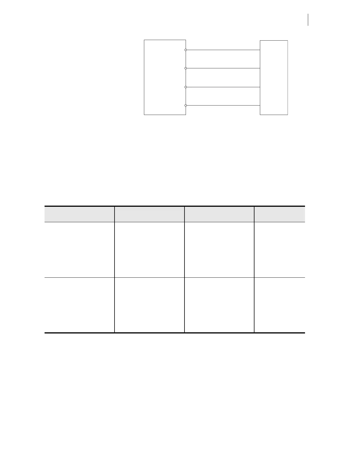
Figure 10.6 Wye Voltage Source Connections
Step 3. Using the front-panel SET/SHOW or the serial port SHOW
command, record the CTRn (where n = VIWDG setting), PTR,
and PHROT setting values.
Step 4. Apply the current and voltage quantities shown in Column 1 of
Table 10.5.
Values are given for PHROT := ABC and PHROT := ACB.
Step 5. Use the front-panel
METER function or the serial port MET
command to verify the results.
Delta-Connected Voltages
Perform the following steps to test delta-connected voltages:
Step 1. Connect the current source to the relay, as shown in Figure 10.4
(VIWDG = 1) or Figure 10.5 (VIWDG = 2).
Step 2. Connect the voltage source to the relay, as shown in
Figure 10.7. Make sure that DELTA_Y := DELTA.
SEL-787
E01
E02
E03
E04
Voltage
Test
Source
VA
VB
VC
VN
Table 10.5 Power Quantity Accuracy—Wye Voltages
a
Applied Currents and Voltages
Real Power
(kW)
Reactive Power (kVAR)
Power Factor
(pf)
PHROT := ABC
IAWn =2.5 ∠−26
IBWn =2.5 ∠−146
ICWn =2.5 ∠+94
Expected:
P = 0.4523 • CTRn • PTR
Expected:
Q = 0.2211 • CTRn • PTR
Expected:
pf = 0.90 lag
VA = 67 ∠0
VB = 67 ∠−120
VC = 67 ∠+120
Measured: Measured: Measured:
PHROT := ACB
IAWn =2.5 ∠−26
IBWn =2.5 ∠+94
ICWn =2.5 ∠−146
Expected:
P = 0.4523 • CTRn • PTR
Expected:
Q = 0.2211 • CTRn • PTR
Expected:
pf = 0.90 lag
VA = 67 ∠0
VB = 67 ∠+120
VC = 67 ∠−120
Measured: Measured: Measured:
a
n = VIWDG setting