2.11
Date Code 20081022 Instruction Manual SEL-787 Relay
Installation
I/O Configuration
Password and
SEL
BOOT Jumper
Selection
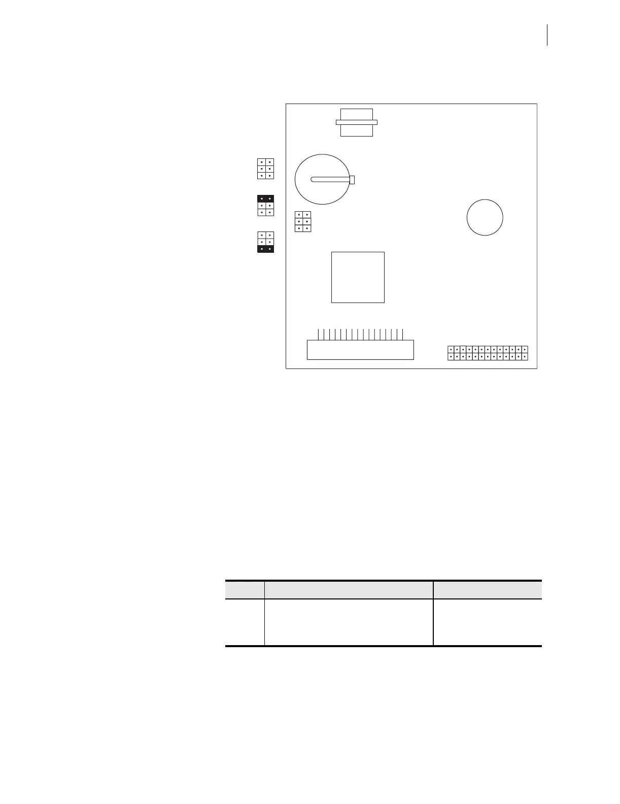
Figure 2.7 shows the major components of the Slot B card in the base unit.
Notice the three sets of pins labeled A, B, and C.
Figure 2.7 Pins for Password Jumper and SELBOOT Jumper
Pins labeled A bypass the password requirement, pins labeled B enable
breaker control, and pins labeled C force the relay to the SEL operating
system called SEL
BOOT. In the unlikely event that the SEL-787 suffers an
internal failure, communications with the relay may be compromised. Forcing
the relay to SEL
BOOT provides a means of downloading new firmware. To
force the relay to SEL
BOOT, position the jumper in Position C, as shown in
Figure 2.7 (SEL
BOOT forced). When forced to SELBOOT, you can only
communicate with the relay via the front-panel port.
To gain access to Level 1 and Level 2 command levels without passwords,
position the jumper in position A, as shown in Figure 2.7 (Password
bypassed). Although you gain access to Level 2 without a password, the alarm
contact still closes momentarily when accessing Level 2. Table 2.10 tabulates
the functions of the three sets of pins and jumper default positions.
Table 2.10 Jumper Functions and Default Positions
Pins Jumper Default Position Description
A Not bypassed (requires password) Password bypass
B Off (breaker control disabled) Enable breaker control
a
a
Enable/Disable serial port, front panel, and Fast Operate commands for breaker control.
C Not bypassed (not forced SELBOOT) Forced SELBOOT
A
B
C
JMP1
A
B
C
JMP1
A
B
C
JMP1
A
B
C
JMP1
Default
Positions
Password
Bypassed
SEL
BOOT
Forced