1-56 Factory-Set Logic Date Code 990215
SEL-351P Manual Técnico
CICLO BLOQUEADO
DWG: MP351P037
RESET
ESTADO DO CONTROLE
LED19 = 79CYLED18 = 79RS LED20 = 79LO
LED19L = NLED18L = N LED20L = N
SEL
OGIC
Setting:
Trip Latch
LED (Y/N)?
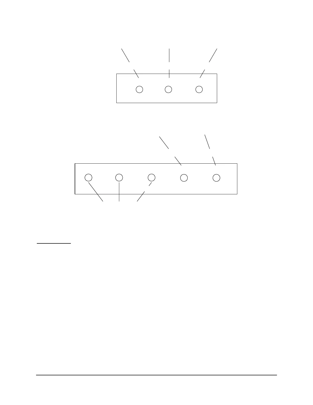
Figure SECTION 1: .47: Front-Panel Reclosing Relay Status LEDs
BC
DWG: MP351P038
A
LED24 = 50G6+50N6
+ 51N1 + 51N2
LED25 = 67N3T
LED25L = Y
N SEF
LED24L = Y
SEL
OGIC
Setting:
Trip Latch
LED (Y/N)?
Fixed-Function,
Trip-Latched LEDs
TIPO DE FALTA
Figure SECTION 1: .48: Front-Panel Fault-Type Trip Target LEDs
Hot Line Tag
Figure SECTION 1: .49 shows the factory-set hot line tag logic. From the factory, latch LT7 is
set such that latch output LT7 is always asserted (Relay Word bit LT7 = logical 1) – the hot line
tag is reset (disabled). The front-panel HOT LINE TAG LED is always extinguished. Relay
Word bit LT7 is also embedded in close logic (CL and ULCL) and drive-to-lockout (79DTL)
SEL
OGIC
factory settings.