Date Code 990215 Inputs, Outputs, Timers, and Other Control Logic 7-5
SEL-351P Manual Técnico
The pickup/dropout timer for input IN102 (IN102D) is set at:
IN102D = 1.00 cycle
to provide input energization/deenergization debounce.
E
XTRA
L
OCAL
C
ONTROL
S
WITCHES
The local control switch feature of this relay replaces traditional panel-mounted control switches.
Operate the eight (8) local control switches using the front-panel keyboard/display (see
Section 11: Additional Front-Panel Interface Details). This extra local control is not the
control available via the operator control pushbuttons on the bottom half of the SEL-351P front
panel.
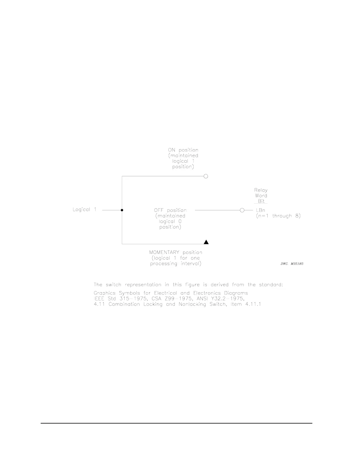
Figure SECTION 7: .3: Local Control Switches Drive Local Bits LB1 Through LB8
The output of the local control switch in
Figure SECTION 7: .3 is a Relay Word bit LBn (n = 1
through 8), called a local bit. The local control switch logic in
Figure SECTION 7: .3 repeats
for each local bit LB1 through LB8. Use these local bits in SEL
OGIC
Control Equations. For a
given local control switch, the local control switch positions are enabled by making
corresponding label settings.