Date Code 990215 Inputs, Outputs, Timers, and Other Control Logic 7-25
SEL-351P Manual Técnico
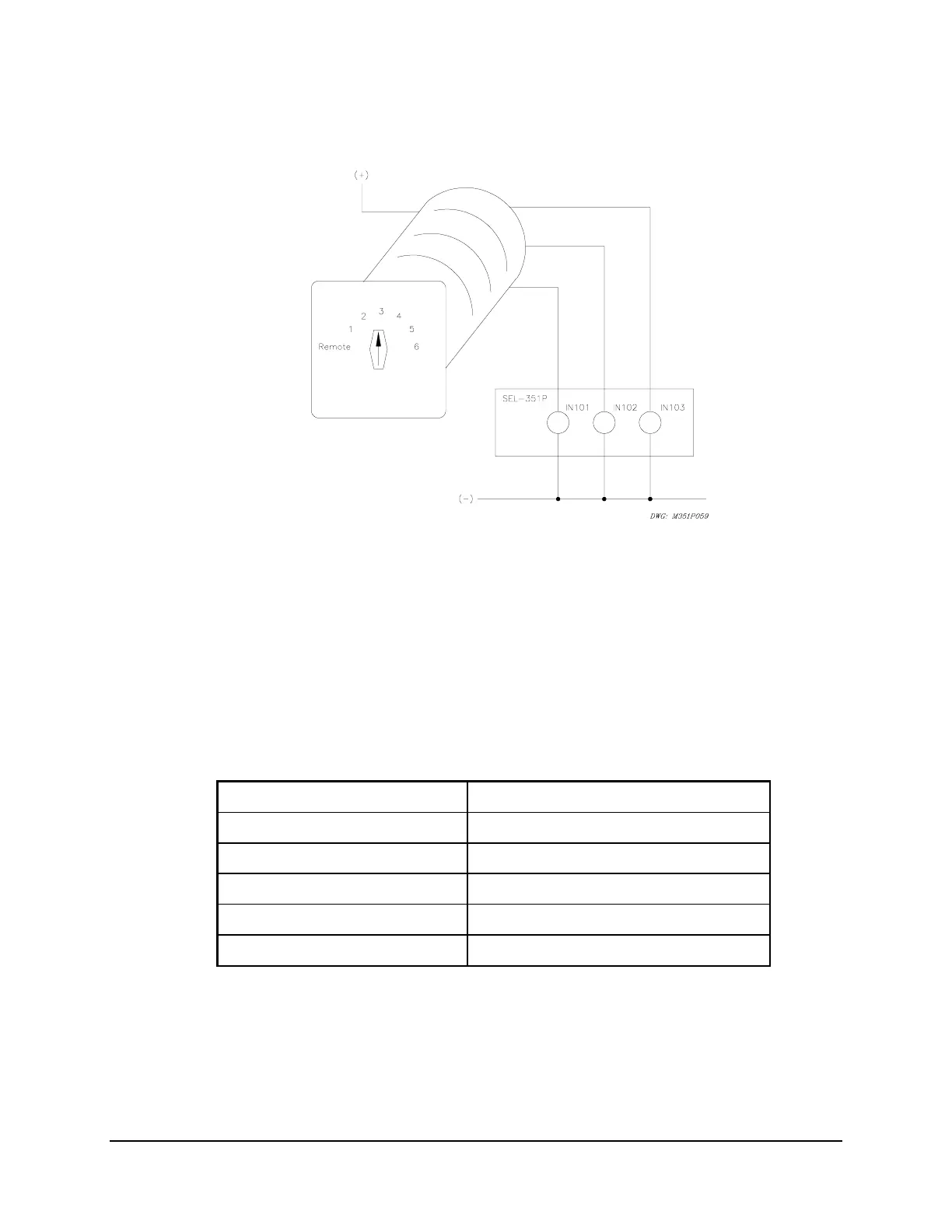
IN102, and IN103 on the relay are connected to a rotating selector switch in Figure SECTION 7:
.21.
Figure SECTION 7: .21: Rotating Selector Switch Connected to Inputs IN101, IN102,
and IN103 for Active Setting Group Switching
The selector switch has multiple internal contacts arranged to assert inputs IN101, IN102, and
IN103, dependent on the switch position. As shown in
Table SECTION 7: .7, when the selector
switch is moved from one position to another, a different setting group is activated. The logic in
Table SECTION 7: .6 is implemented in the SEL
OGIC
Control Equation settings in
Table SECTION 7: .7.
Table SECTION 7: .7: SEL
OGIC
Control Equation Settings for Rotating Selector Switch
Active Setting Group Switching
SS1 = !IN103 * !IN102 * IN101 = NOT(IN103) * NOT(IN102) * IN101
SS2 = !IN103 * IN102 * !IN101 = NOT(IN103) * IN102 * NOT(IN101)
SS3 = !IN103 * IN102 * IN101 = NOT(IN103) * IN102 * IN101
SS4 = IN103 * !IN102 * !IN101 = IN103 * NOT(IN102) * NOT(IN101)
SS5 = IN103 * !IN102 * IN101 = IN103 * NOT(IN102) * IN101
SS6 = IN103 * IN102 * !IN101 = IN103 * IN102 * NOT(IN101)
The settings in Table SECTION 7: .7 are made in each setting Group 1 through 6.
Selector Switch Starts Out in Position 3
Refer to
Table SECTION 7: .7 and Figure SECTION 7: .22.