Date Code 990215 Setting Negative-Sequence Overcurrent Elements F-5
SEL-351P Manual Técnico
Figure APPENDIX F: .3 shows traditional phase overcurrent element coordination between the
feeder relay and line recloser phase overcurrent elements. Phase overcurrent elements must
accommodate load and cold load pickup current. The 450 A maximum feeder load current limits
the sensitivity of the feeder phase overcurrent element, 51F, to a pickup of 600 A. The feeder
relay cannot back up the line recloser for phase faults below 600 A.
Apply the Feeder Relay Negative-Sequence Overcurrent Element (Guidelines 1 to 3)
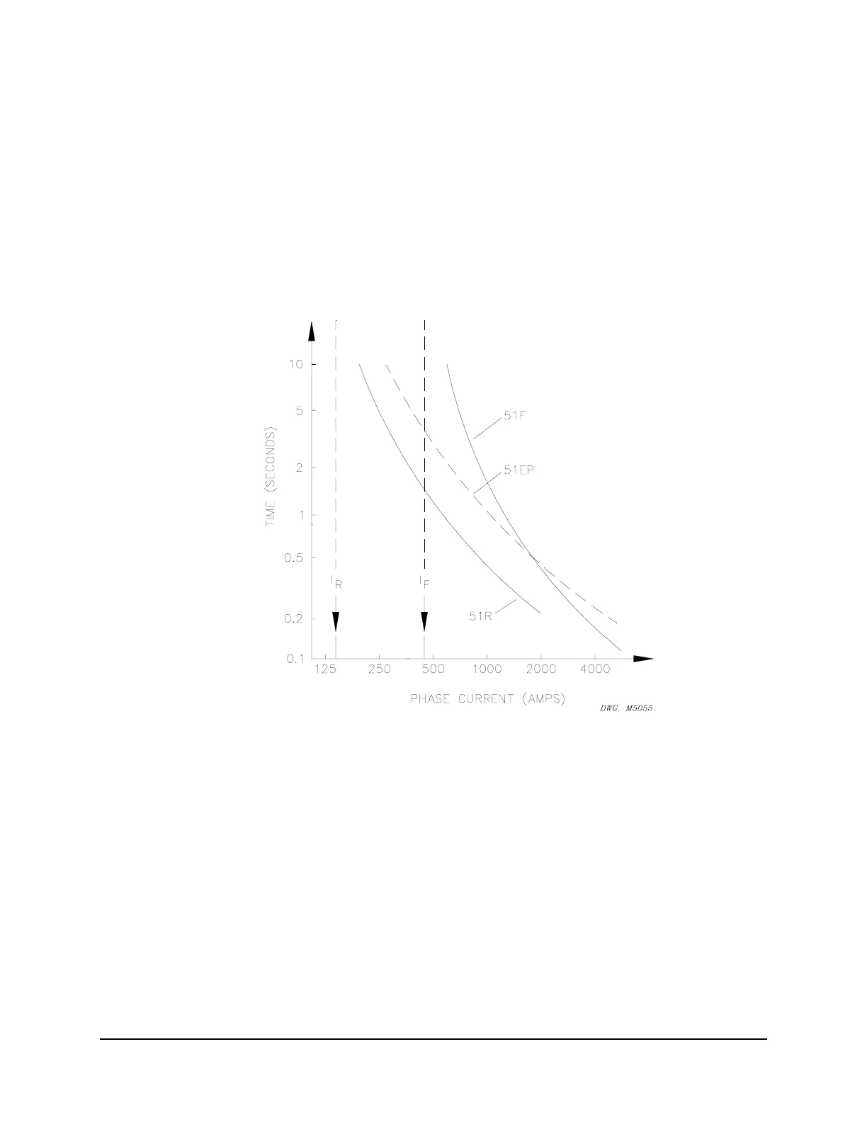
Applying negative-sequence overcurrent element coordination Guidelines 1 to 3 results in the
feeder relay “equivalent” phase overcurrent element (51EP) in
Figure APPENDIX F: .4. Curve
for 51F is shown for comparison only.
Figure APPENDIX F: .4: Phase-to-Phase Fault Coordination
51EP: pickup = 300 A (below max. feeder load, I
F
)
Considerable improvement in sensitivity and speed of operation for phase-to-phase faults is
achieved with the 51EP element. The 51EP element pickup of 300 A has twice the sensitivity of
the 51F element pickup of 600 A. The 51EP element speed of operation for phase-to-phase
faults below about 2000 A is faster than that for the 51F element.
Convert “Equivalent” Phase Overcurrent Element Settings to Negative-
Sequence Overcurrent Element Settings (Guideline 4)
The “equivalent” phase overcurrent element (51EP element in Figure APPENDIX F: .4)
converts to true negative-sequence overcurrent element settings (51QF in
Figure APPENDIX F:
.5) by applying the equation given in Guideline 4. The time dial (lever) and curve type of the