G-6 Setting SEL
OGIC
®
Control Equations Date Code 990430
SEL-351P Manual Técnico
The Relay Word bits in this setting example are:
51P1 Maximum phase current above pickup setting 51P1P for phase time-overcurrent
element 51P1T (see Figure 3.14)
51G1 Maximum residual ground current above pickup setting 51G1P for residual ground
time-overcurrent element 51G1T (see Figure 3.19)
OUT103 Output contact OUT103 is set as a breaker failure trip output (see Output Contacts
in
Section 7: Inputs, Outputs, Timers, and Other Control Logic
)
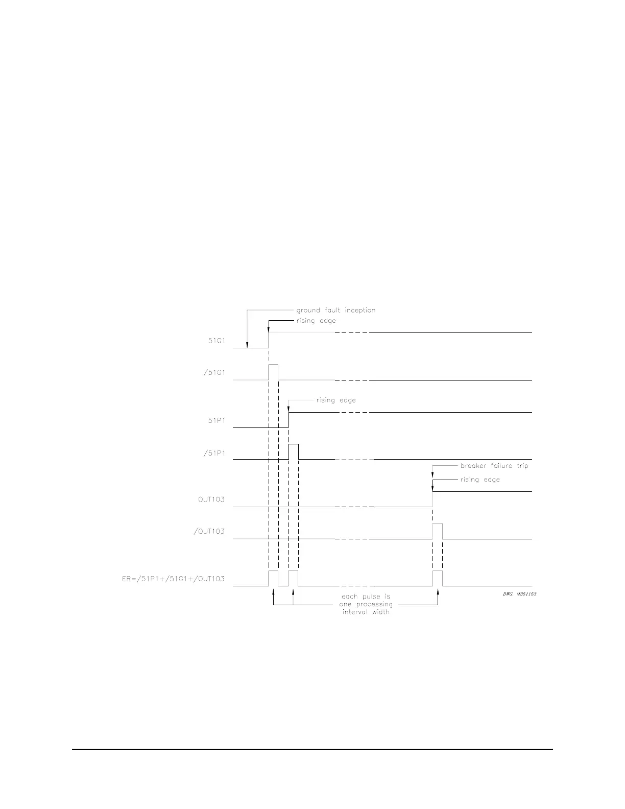
When setting ER sees a logical 0 to logical 1 transition, it generates an event report (if the relay
is not already generating a report that encompasses the new transition). The rising edge
operators in the above factory setting example allow setting ER to see each transition
individually.
Suppose a ground fault occurs and a breaker failure condition finally results.
Figure APPENDIX
G: .1 demonstrates the action of the rising edge operator / on the individual elements in setting
ER.
Figure APPENDIX G: .1: Result of Rising Edge Operators on
Individual Elements in Setting ER
Note in Figure APPENDIX G: .1 that setting ER sees three separate rising edges, due to the
application of rising edge operators /. The rising edge operator / in front of a Relay Word bit
sees this logical 0 to logical 1 transition as a “rising edge” and the resultant asserts to logical 1
for one processing interval. The assertions of 51G1 and 51P1 are close enough that they will be