Installation FLSE100-XT
FLOWSIC100 Flare-XT · Operating Instructions · 8023761/V 1-0/2020-10 · © SICK Engineering GmbH 73
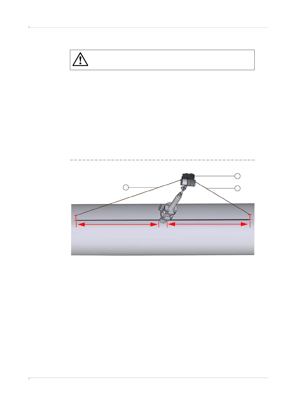
Alignment of the device to the flow direction using a laser
1 Mark the pipe center one meter before and after probe version F1F-P, e.g. with chalk or
a felt pen, see → Fig. 38.
2 Place a laser on the side of the electronics housing and let the laser beam hit the pipe at
the level of the end of the first marking.
3 Measure the distance between the point of impact of the laser and the marking on the
pipeline.
4 Repeat the procedure for the second marking.
5 Align the electronics housing so that distance a corresponds approximately to
distance b.
The maximum permissible difference between value a and value b is 10 mm.
6 After alignment, tighten the self-cutting ring fitting 1.25 turns.
Make sure the markings for the self-cutting ring fitting are next to each other again,
→ Fig. 35.
Fig. 38 Alignment of probe version F1F-P
WARNING: Risk of explosion
The laser may only be used if no Ex atmosphere is present. Use of the laser is
not permitted under Ex conditions.
a b
Marking: 1 m Marking: 1 m
1
2
2
1 Laser
2 Laser beam