Assembly and Installation
FLOWSIC100 · Operating Instructions · 8012513/YSA5/V2-1/2016-07 · © SICK Engineering GmbH 89
Subject to change without notice
Electrical installation
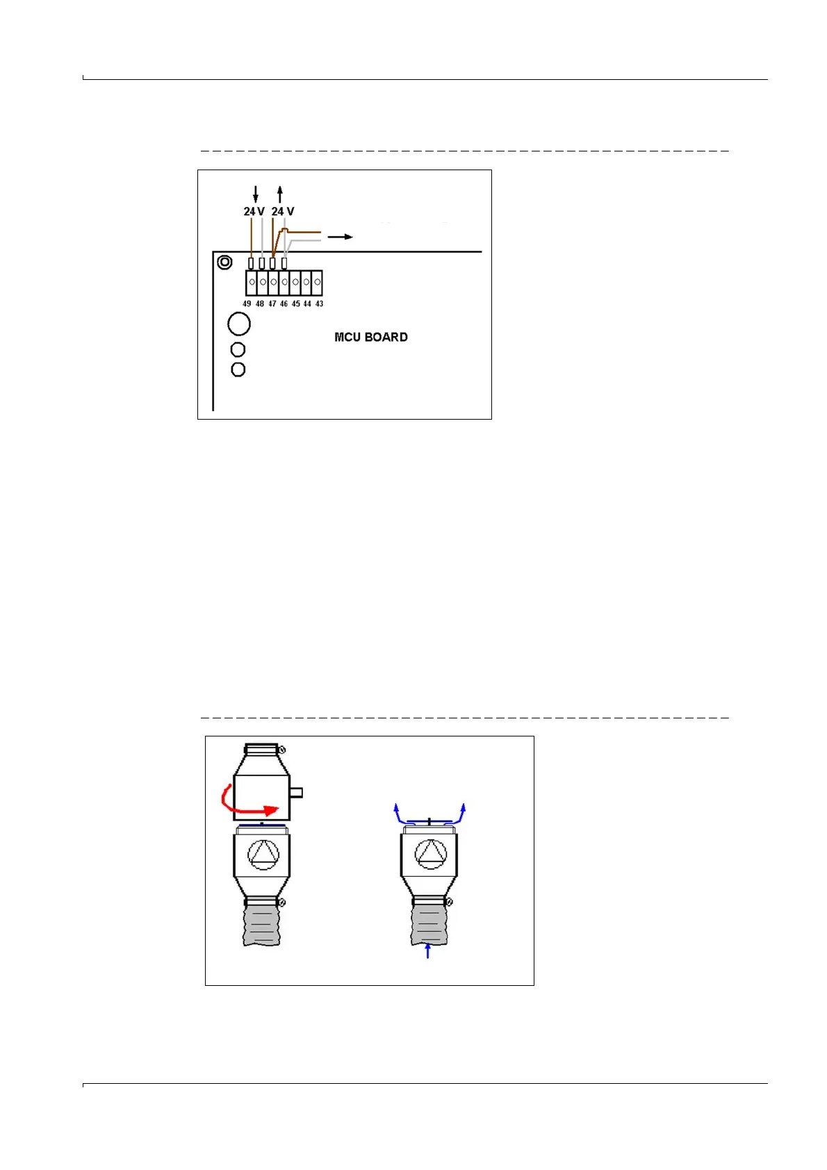
Fig. 58 Solenoid valve electrical connection
Make a 2-wire connection to the solenoid valve (blade terminal). There are no
requirements on polarity because the pulling magnet is electrically isolated from the valve
body.
Pulling magnet connection values: 24 V DC; 0.43 A continuous current.
Function test in normal operation with MCU blower unit
a) Start the blower by switching the MCU on.
When using the optionally available "cooling air control for device types M-AC and H-AC",
start blower operation in a suitable manner; e.g. with a fixed blower connection on the 24 V
rail or bridging the relay.
b) Remove the emergency air valves (
p. 89, Fig. 59) and start the MCU blower.
The blowing air flow must lift the valve plate evenly approx. 2 mm out of its seating and the
cooling air flow passing through must be clearly felt. When necessary, close off the other
line.
Lift the valve plate mechanically when the valve sticks in its seating (long storage time).
Then repeat the test to ensure the blower can open the valve on its own.
Fig. 59 Removing and throughflow test on the emergency air valves
a) Valve open
b) Air test / opening control