90 FLOWSIC100 · Operating Instructions · 8012513/YSA5/V2-1/2016-07 · © SICK Engineering GmbH
Assembly and Installation
Subject to change without notice
Function test emergency air operation with instrument air
Make a compressed air connection between the junction box for solenoid valve (2) and
emergency air valve (3) as shown in (
p. 87, Fig. 57).
Separate the emergency air valve from the cooling air hoses and S/R units.
Switch the MCU supply voltage off - solenoid valve (2a) must switch audibly and release
the instrument air flow.
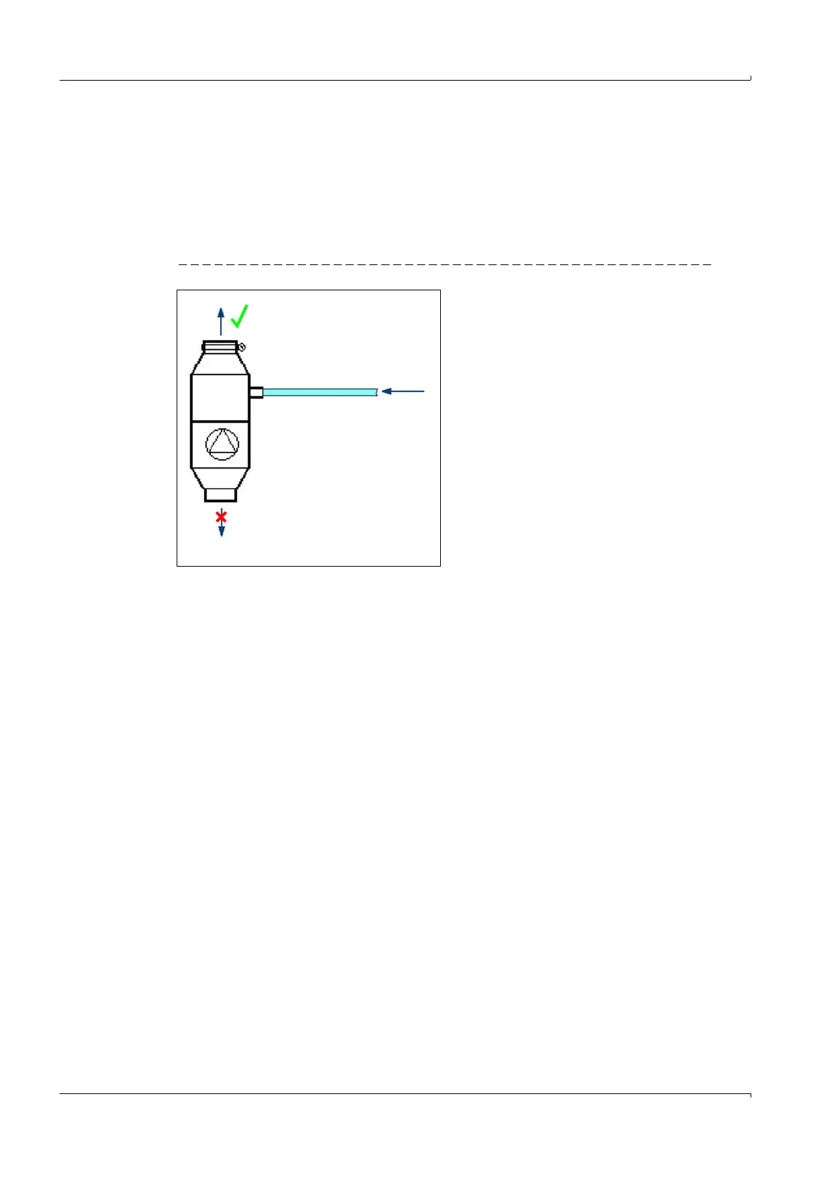
Emergency air flow direction test - see (
Fig. 60).
Fig. 60 Emergency air direction test
The air flow in flow direction must be noticeable (approx. 2.8 l/s). No significant leakage
flow should flow in the blocking direction (
Fig. 60). Leakage rates up to 3% of the nominal
air flow are allowed.
Repeat the test shown in Fig. 60 with the S/R unit connected (
p. 87, Fig. 57). The escaping
air should still also be clearly felt on the probe exhaust slots (
p. 87, Fig. 57).
Finally, reconnect all connections as shown in (
p. 87, Fig. 57), reset any changed
parameters and set the device to the operating state.
Maintenance
The emergency air supply should be able to bridge temporary cooling air failures up to 24
hours. Measuring operation could be interrupted during this time (noise disturbance due to
increased instrument air noise).
It is recommended to take the S/R units out of the sample gas duct during longer term
restrictions or complete failure of the standard cooling air supply.
Check parts carrying air as shown in (
p. 87, Fig. 57) after longer emergency air operation:
Remove the DN 25 cooling air hoses and check the insides for condensate, oil and
general contamination. Clean the insides of the hoses when necessary and replace
hoses with heavy contamination. Use hoses with the same length for both S/R units.
Remove the emergency air valves and open to check (
p. 89, Fig. 59).
Remove any contamination and dry the valve, replace emergency air valve (3) when
contamination is heavy or when the valve is damaged (spring, valve plate, rubber seal).
Apply talcum powder to the dry rubber seal of the valve plate to prevent the valve plate
sticking in the seating.
Carry out the opening and blocking direction function check as shown in (
p. 90, Fig.
60).
Direction test
emergency air
Flow direction
Blocking direction