Product Description
FLOWSIC600 · Technical Information · 8010125 V 4.0 · © SICK AG 33
Subject to change without notice
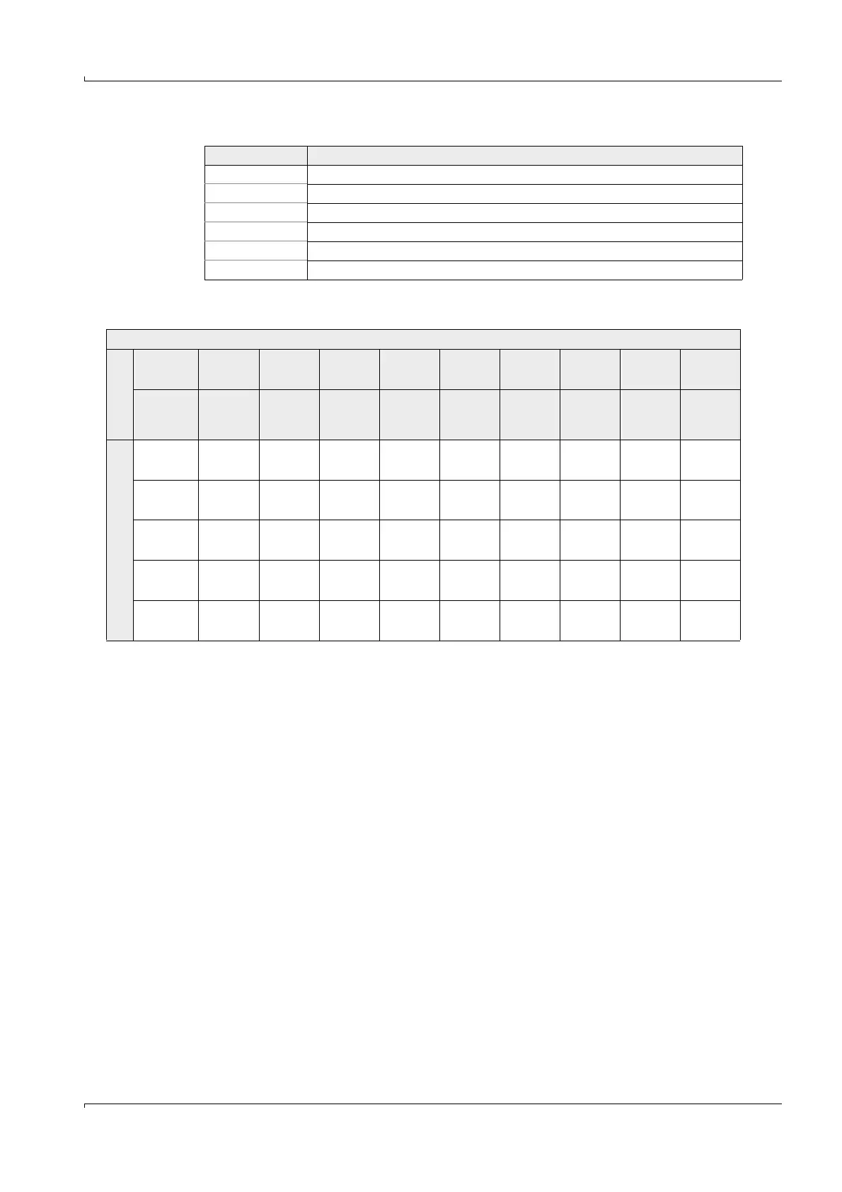
Table 2 Possible sources for analog output and impulse output
Table 3 Hardware variant / output configuration without integrated Electronic Volume Corrector (EVC)
Reg. Measurement output
#7001 Flow rate at flowing conditions (a.c.)
#7002 Flow rate at base conditions (s.c.)
#7003 Speed of sound (SOS) (averaged over paths)
#7004 Velocity of gas (VOG) (averaged over paths)
#7046 Molar mass
#7047 Mass flow
Hardware variant/Output configuration
1
1
X(Y/Z):
X = Code for hardware variant and output configuration within the new internal Key Code.
Y = Code for hardware variant within the Key Code (
pg. 207, Figure 97).
Z = Code for output configuration.
Analog board
Standard 1 (1/1) 2 (1/2) 3 (1/3) 4 (2/4) 5 (2/4) 6 (2/5) 7 (2/5) 9 (4/7) 0 (4/2)
Low
pressure
E (7/1) F (7/2) G (7/3) H (8/4) I (8/4) J (8/5) K (8/5) L (9/7) Q (9/2)
Output terminal
31/32 Pulse Pulse Status Analog
Analog/
HART
Analog
Analog/
HART
Analog Pulse
33/34 RS485 RS485 RS485 RS485 RS485 RS485 RS485 RS485 RS485
51/52 Pulse Pulse Pulse Pulse Pulse Status Status Pulse Pulse
41/42 Status Status Status Status Status Status Status Status Status
81/82 Status RS485 Status Status Status Status Status RS485 RS485

 Loading...


