•
Pr
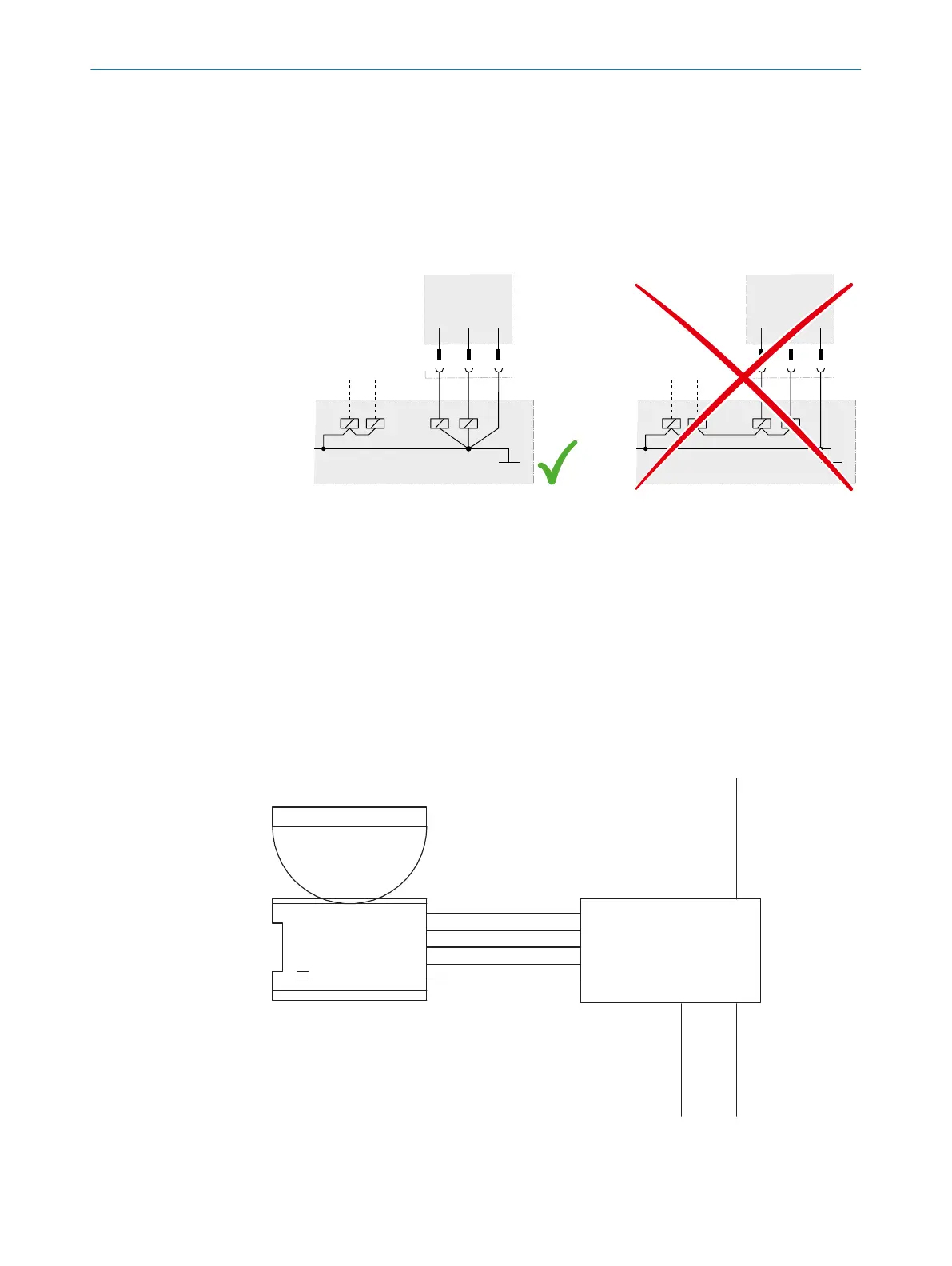
event the formation of a potential difference between the load and the protec‐
tive device. If you connect loads to the OSSDs (safety outputs) that then also
switch if controlled with negative voltage (e.g., electro-mechanical contactor with‐
out reverse polarity protection diode), you must connect the 0 V connections of
these loads and those of the corresponding protective device individually and
directly to the same 0 V terminal strip. In the event of a fault, this is the only way to
ensure that there can be no potential difference between the 0 V connections of
the loads and those of the corresponding protective device.
Figure 34: No potential difference between load and protective device
Requirements for the electrical control of the machine
T
he OSSDs are short-circuit protected to 24 V DC and 0 V. When the protective field is
clear, the OSSDs signal the ON state with the HIGH signal level (non-isolated). If there
are objects in the protective field or there is a device fault, the OSSDs signal the OFF
state with the LOW signal level.
4.4.5 Connection diagrams
FE on the M12 plug connector
T
he safety laser scanner can be integrated via an AIDA-compliant fieldbus module. In
the example, the functional earth is connected to the M12 plug connector.
microScan3
Core I/O AIDA
+24 V DC
OSSD 1.B
OSSD 1.A
0 V DC
FE
FE
FE 0 V DC
+24 V DC
+24 V DC
+24 V DC
In0
F
E
0 V DC
In1
FE 0 V DC
AIDA
Field bus module
Figure 35: Connection diagram with FE on the M12 plug connector
4 P
ROJECT PLANNING
50
O P E R A T I N G I N S T R U C T I O N S | microScan3 Core I/O AIDA 8017784/1ELL/2022-01-21 | SICK
Subject to change without notice

 Loading...


