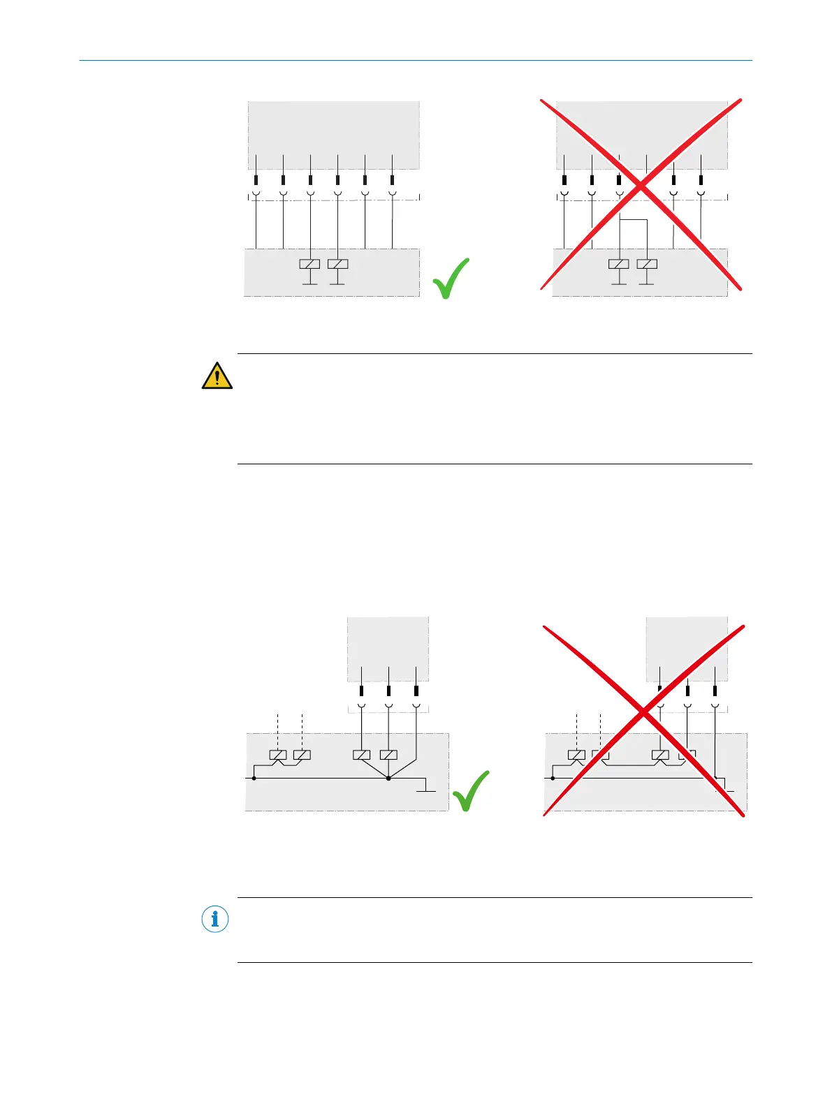
Figure 40: Connection of the OSSDs of an OSSD pair
DANGER
H
azard due to lack of effectiveness of the protective device
The dangerous state may not be stopped in the event of non-compliance.
b
Prevent the formation of a potential difference between the load and the protec‐
tive device.
b
If y
ou connect loads to the OSSDs (safety outputs) that then also switch if con‐
trolled with negative voltage (e.g., electro-mechanical contactor without reverse
polarity protection diode), you must connect the 0 V connections of these loads
and those of the corresponding protective device individually and directly to the
same 0 V terminal strip. In the event of a fault, this is the only way to ensure that
there can be no potential difference between the 0 V connections of the loads and
those of the corresponding protective device.
Figure 41: No potential difference between load and protective device
6.2 Connection overview
NOTE
T
he USB connection may only be used temporarily and only for configuration and
diagnostics.
6 ELECTRICAL INSTALLATION
60
O P E R A T I N G I N S T R U C T I O N S | microScan3 Core I/O AIDA 8017784/1ELL/2022-01-21 | SICK
Subject to change without notice

 Loading...


