b
Mak
e sure that the safety laser scanner’s field of view is not restricted.
b
Make sure that there are not mirrors or other very reflective objects in the protec‐
tive field.
b
Make sure that no small objects (e.g. cables) are in the protective field, even if the
safety outputs do not switch to the OFF state as a result.
b
Mount the safety laser scanner so that the status indicators are clearly visible.
b
Mount the safety laser scanner so that you can plug in and pull out the system
plug.
b
Take appropriate measures for vibration damping if vibration and shock specifica‐
tions exceed the values and test conditions specified in the data sheet, see "Data
sheet", page 126.
b
For machines that vibrate heavily, use thread-locking compounds to prevent the
possibility of fixing screws coming loose unintentionally.
b
Make sure that the safety laser scanner is aligned correctly, even during mount‐
ing: if the safety laser scanner is intended to monitor an area of 270° on a corner,
the safety laser scanner may be mounted rotated by a maximum of 2.5° about the
vertical axis.
b
Location of the scan plane: see "Dimensional drawings", page 134.
b
Take account of the tightening torque for the fixing screws:
°
M5 at rear/at side = 4.5 Nm … 5.0 Nm
°
M4 at rear/at side = 2.2 Nm … 2.5 Nm
Higher tightening torques may damage the thread. Lower tightening torques do
no
t offer sufficient protection against slipping of the safety laser scanner due to
vibrations, for example.
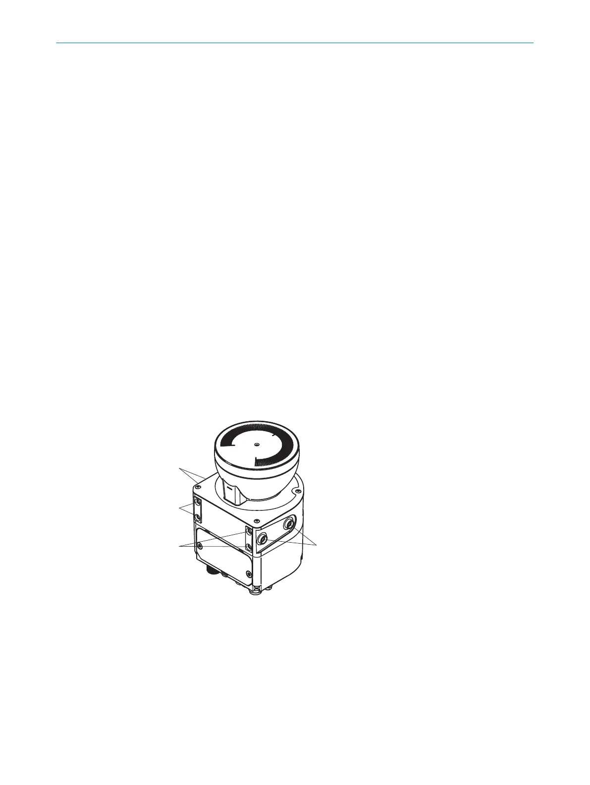
5.3.1 Direct mounting
The safety laser scanner has 4 M5 threaded holes on the back. If you are able to drill
through the mounting surface from the rear, you can mount the safety laser scanner
directly using these threaded holes.
Figure 39: Mounting the safety laser scanner directly
1
Rear M5 threaded hole
2
Side M5 threaded hole
b
Use eit
her the rear or the side M5 threaded holes for direct mounting, see
figure 39, page 58.
b
Use all four rear or all 4 side M5 threaded holes for direct mounting, so that the
values given in the data sheet for vibration and shock resistance are achieved.
b
Maximum depth of thread engagement: 7.5 mm (see "Dimensional drawings",
page 134).
b
Tightening torque: 4.5 Nm to 5.0 Nm.
5 MOUN
TING
58
O P E R A T I N G I N S T R U C T I O N S | microScan3 Core I/O AIDA 8017784/1ELL/2022-01-21 | SICK
Subject to change without notice

 Loading...


