EasyManuals Logo

SICK microScan3 Core I/O AIDA User Manual

SICK microScan3 Core I/O AIDA
152 pages
To Next Page IconTo Next Page
To Previous Page IconTo Previous Page
Page #86 background imageLoading...
Page #86 background image
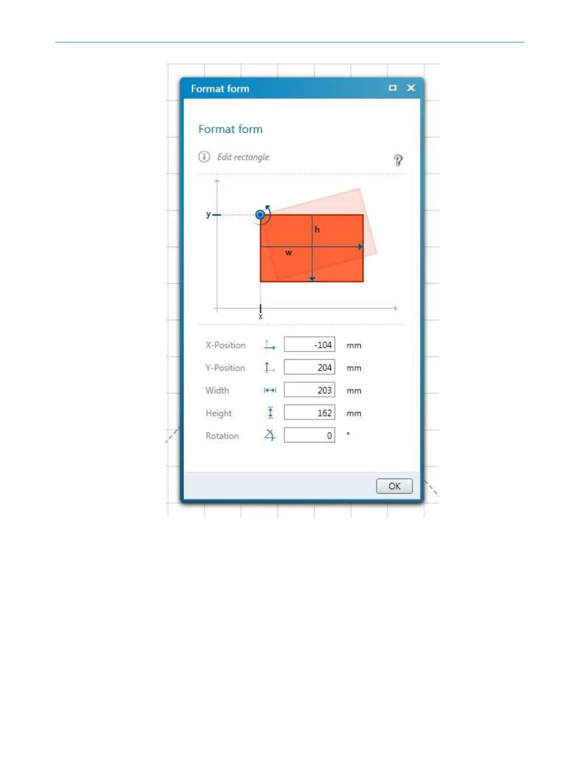
Figure 54: Editing fields using coordinates
T
he reference points for the X and Y values are as follows:
Rectangle: top left corner
Circle: center point
Circle sector: center point
Polygon: each point individually
Contour line: each point individually
7.9.7 Drawing in points that cannot be monitored
The area to be monitored is scanned radially 1. F
or this reason, shadows 3 are
formed by objects in the room 2 (support columns, separator grids, etc.). The safety
laser scanner cannot monitor these areas.
7 C
ONFIGURATION
86
O P E R A T I N G I N S T R U C T I O N S | microScan3 Core I/O AIDA 8017784/1ELL/2022-01-21 | SICK
Subject to change without notice

Table of Contents

Other manuals for SICK microScan3 Core I/O AIDA

Questions and Answers:

Question and Answer IconNeed help?

Do you have a question about the SICK microScan3 Core I/O AIDA and is the answer not in the manual?

SICK microScan3 Core I/O AIDA Specifications

General IconGeneral
Scanning angle275°
Protection classIP65
Configuration methodSOPAS ET
Enclosure ratingIP65
Dimensions102 mm x 152 mm x 106 mm
Scanning range5.5 m
Protective field range5.5 m
Number of monitoring cases128
Supply voltage24 V DC
Performance levelPL e (ISO 13849-1)
Warning field range5.5 m
Resolution for safety field30 mm / 40 mm / 50 mm / 70 mm
Connection typeM12
Protective field resolution30, 40, 50, 70 mm
Number of protective fields128

Related product manuals