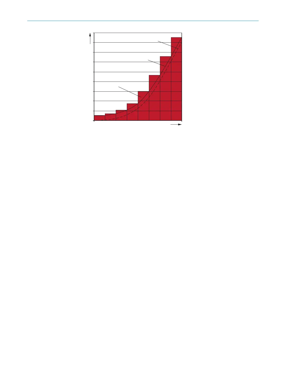
Figure 30: Stopping distance as a function of the vehicle’s speed
v speed
S
A
stopping distance
Z supplements
S
L
protective field length for the relevant range of speeds
S
A
= S
Br
+ S
AnF
+ S
AnS
wher
e
:
•
S
A
= stopping distance in millimeters (mm)
•
S
Br
= braking distance, from the vehicle documentation, in millimeters (mm)
•
S
AnF
= distance covered during the vehicle control’s response time (including
signal propagation time), from the vehicle documentation, in millimeters (mm)
•
S
AnS
= distance covered during the safety laser scanner’s response time in milli‐
meters (mm)
The distance S
AnS
depends on t
he s
afety laser scanner’s response time and the
vehicle’s speed. The distance S
AnS
is calculated using the following formula:
S
AnS
= t
R
× V
ma
x
wher
e:
°
t
R
= s
af
ety laser scanner’s response time in seconds (s) (see "Response
times", page 131)
°
V
max
= maximum speed of the vehicle, from the vehicle documentation, in
millimeters per second (mm/s) (If you define a number of monitoring cases
with different protective fields: V
max
= maximum speed of the vehicle in the
current monitoring case)
4.3.8.2 Protective field width
The protective field must be wide enough to cover the width of the loaded vehicle with
supplements f
or measurement error and the lack of ground clearance. When calculat‐
ing the protective field width, the impact of turning must be considered separately.
Supplement Z
R
for reflection-based measurement errors
All devices: If there is a retroreflector in the vicinity of the protective device (distance
of the retroreflector from protective field ≤ 6 m), you must take the supplement Z
R
=
350 mm into account.
4 PROJECT PLANNING
44
O P E R A T I N G I N S T R U C T I O N S | microScan3 Core I/O AIDA 8017784/1ELL/2022-01-21 | SICK
Subject to change without notice

 Loading...


