7.8 Reference contour field
Overview
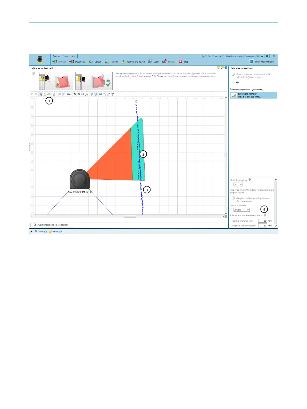
Figure 51: Reference contour field
1
Tool for drawing reference contour fields
2
Drawn contour with tolerance band
3
Visible spatial contour
4
Configure the field
If you have activated the R
eference contour monitoring option for a monitoring plane, the
Reference contour field dialog box is displayed. Draw the reference contour field based
on the values determined during project planning (see "Reference contour monitoring",
page 25).
The contour as reference field monitors a contour of the environment. The safety laser
scanner switches all safety outputs to the OFF state if a contour does not match the set
parameters, because, for example, the mounting of the safety laser scanner has been
changed.
Drawing a reference contour field
1.
Select the tool for drawing reference contour fields.
2. Draw a line along the spatial contour as a reference.
b
First, use the mouse to click the desired contour.
b
Click to add the corners of the contour.
b
Finally, double-click the contour.
✓
The reference contour field is displayed.
7 C
ONFIGURATION
78
O P E R A T I N G I N S T R U C T I O N S | microScan3 Core I/O AIDA 8017784/1ELL/2022-01-21 | SICK
Subject to change without notice

 Loading...


