Inrush Current Detection
If large inrush currents are expected when using the protection device at transformers, the inrush current
detection can be activated in the 7SC80.
The general setting notes for the inrush current detection are described in Section 2.12.1.8 Setting Notes.
The inrush current detection can be enabled and disabled in elements at addresses:
67-1 element Address 2215 67-1 w. Inrush
67-2 element Address 2216 67-2 w. Inrush
67-3element Address 1538 67-3 w. Inrush
67-TOC element Address 2217 67-TOC w. Inru.
67-TOC-1 element Address 2230 67-TOC-1 w. In.
67-TOC-2 element Address 2231 67-TOC-2 w. In.
67-TOC-3 element Address 2232 67-TOC-3 w. In.
67-TOC-4 element Address 2233 67-TOC-4 w. In.
67N-3 element Address 2218 67N-1 w. Inrush
67N-2 element Address 2219 67N-2 w. Inrush
67N-1element Address 1638 67N-3 w. Inrush
67N-TOC element Address 2220 67N-TOC w. Inr.
67N-TOC-1 element Address 2234 67N-TOC-1 w. I.
67N-TOC-2 element Address 2235 67N-TOC-2 w. I.
67N-TOC-3 element Address 2236 67N-TOC-3 w. I.
67N-TOC-4 element Address 2237 67N-TOC-4 w. I.
Manual Close Mode (phases, ground)
When a circuit breaker is closed onto a faulted line, a high speed trip by the circuit breaker is often desired. For
overcurrent or high-set element the delay may be bypassed via a Manual Close pulse, thus resulting in instan-
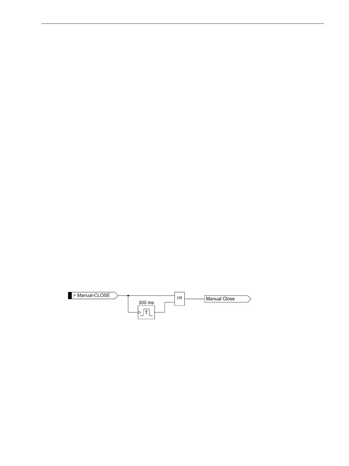
taneous tripping. The internal "Manual close" signal is built from the binary input signal
>Manual Close
(no.
356). The internal "Manual close" signal remains active as long as the binary input signal
>Manual Close
is
active, but at least for 300 ms (see the following logic diagram). To enable the device to react properly on
occurrence of a fault in the phase elements after manual close, address 1513 MANUAL CLOSE has to be set
accordingly. Accordingly, address 1613 MANUAL CLOSE is considered for the ground path address. Thus, the
user determines for both elements, the phase and the ground element, what pickup value is active with what
delay when the circuit breaker is closed manually.
[lo_7sj6-hand-ein, 1, en_US]
Figure 2-36 Manual close feature
External Control Switch
If the manual close signal is not from the 7SC80 device, that is, neither sent via the built-in operator interface
nor via a serial port but directly from a control acknowledgment switch, this signal must be passed to a 7SC80
binary input, and configured accordingly (
>Manual Close
), so that the element selected for MANUAL
CLOSE can become effective. Inactive means that all elements (phase and ground) operate with the config-
ured trip times even with manual close.
Internal Control Function
The manual closing information must be allocated via CFC (interlocking task-level) using the CMD_Information
block, if the internal control function is used.
Functions
2.3 Directional Overcurrent Protection 67, 67N
SIPROTEC Compact, 7SC80, Manual 133
E50417-G1140-C486-A8, Edition 07.2017