Overvoltage Protection 59
Function
The overvoltage protection has two elements. In case of a high overvoltage, tripping switch off is performed
with a short-time delay, whereas in case of less severe overvoltages, the tripping is performed with a longer
time delay. When one of the adjustable settings is exceeded, the 59 element picks up and trips after an adjust-
able time delay has elapsed. The time delay is not dependent on the magnitude of the overvoltage.
The dropout ratio for the two overvoltage elements (= V
dropout value
/V
pickup value
) can be set.
The pickup voltages and time delays can also be set phase-specifically.
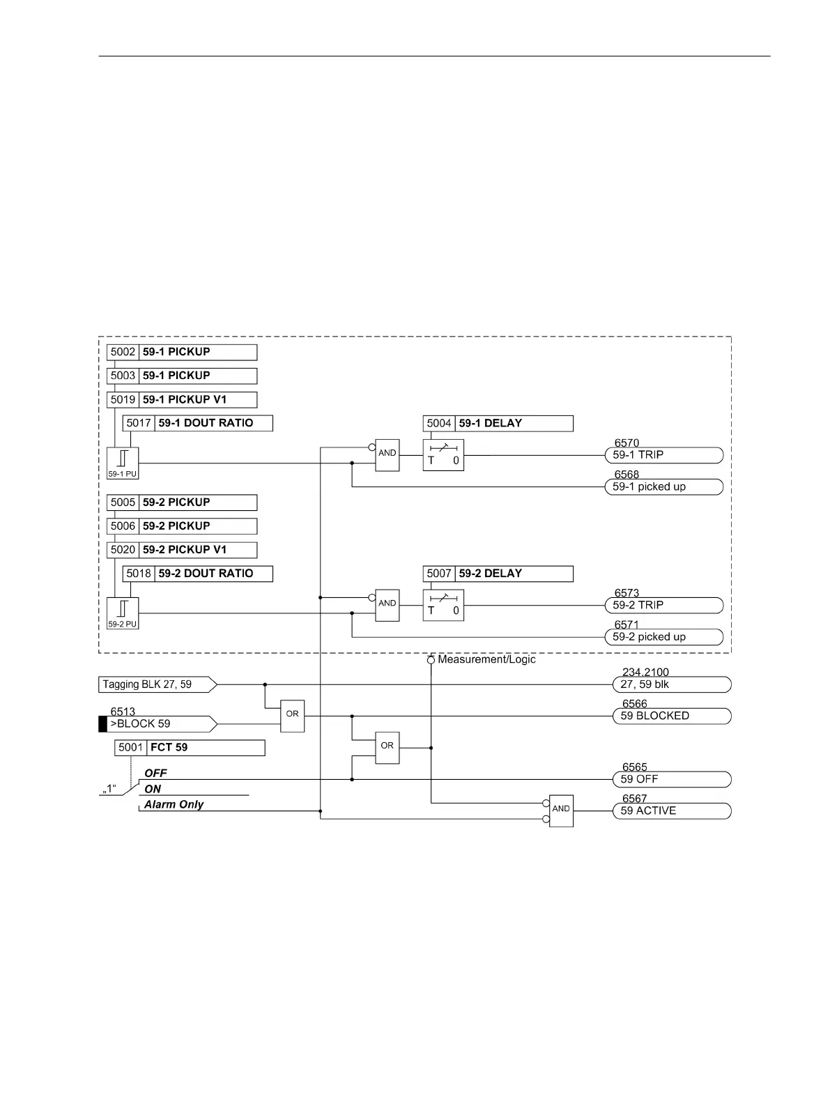
The following figure shows the logic diagram of the overvoltage protection function.
The logic diagram also applies to setting the phase-specific overvoltage protection (Vphph selective or
Vph-n selective). The threshold values and time delays have to be replaced with the phase-specific
values.
[7sc80-ueberspgs-schutz-20130115, 1, en_US]
Figure 2-48
Logic Diagram of the Overvoltage Protection
Undervoltage Protection 27
Function
Undervoltage protection consists of two definite time elements (27-1 PICKUP and 27-2 PICKUP). There-
fore, tripping can be time-coordinated depending on how severe voltage collapses are. Voltage thresholds and
time delays can be set individually for both elements.
The pickup voltages and time delays can also be set phase-specifically.
2.6.2
2.6.3
Functions
2.6 Voltage Protection 27, 59
SIPROTEC Compact, 7SC80, Manual 189
E50417-G1140-C486-A8, Edition 07.2017