If the frequency protection of side 2 is used for load shedding purposes, the setting values depend on the
actual power system conditions. Normally, a time coordinated load shedding is required when taking into
account the importance of the consumers or consumer groups.
Further application examples exist in the field of power stations. Here too, the frequency values to be set
mainly depend on the specifications of the power system operator or the power station operator. The under-
frequency protection of side 2 safeguards the power station's own demand by disconnecting it from the
power system on time. The turbo governor regulates the machine set to the nominal speed. Consequently, the
station's own demands can be continuously supplied at nominal frequency.
Under the assumption that the apparent power is reduced by the same degree, turbine-driven generators can,
as a rule, be continuously operated down to 95 % of the nominal frequency. However, for inductive
consumers, the frequency reduction not only means an increased current input, but also endangers the stable
operation. For this reason, only a short-term frequency reduction down to about 48 Hz (for fN = 50 Hz) or 58
Hz (for fN = 60 Hz) is permissible.
A frequency increase can, for example, occur due to a load shedding or malfunction of the speed regulation
(e.g. in an island network). In this way, the frequency increase protection can, for example, be used as an
overspeed protection.
Dropout Thresholds
The dropout threshold is defined via the adjustable dropout-difference address 5907 DO differential. It
can thus be adjusted to the network conditions. The dropout difference is the absolute-value difference
between pickup threshold and the dropout threshold. The default value of 0.04 Hz can usually remain. Should,
however, frequent minor frequency fluctuations be expected, this value should be increased.
NOTE
The dropout difference of frequency protection of side 2 can be set from 0.04 Hz to 1.00 Hz, while the one
of side 1 can be set from 0.02 Hz to 1.00 Hz.
Time Delays
The delay times 81-1 DELAY S2 to 81-4 DELAY S2 (addresses 5910, 5913, 5916 and 5919) allow the
frequency elements to be time coordinated, e.g. for load shedding equipment. The set times are additional
delay times not including the operating times (measuring time, dropout time) of the protection function.
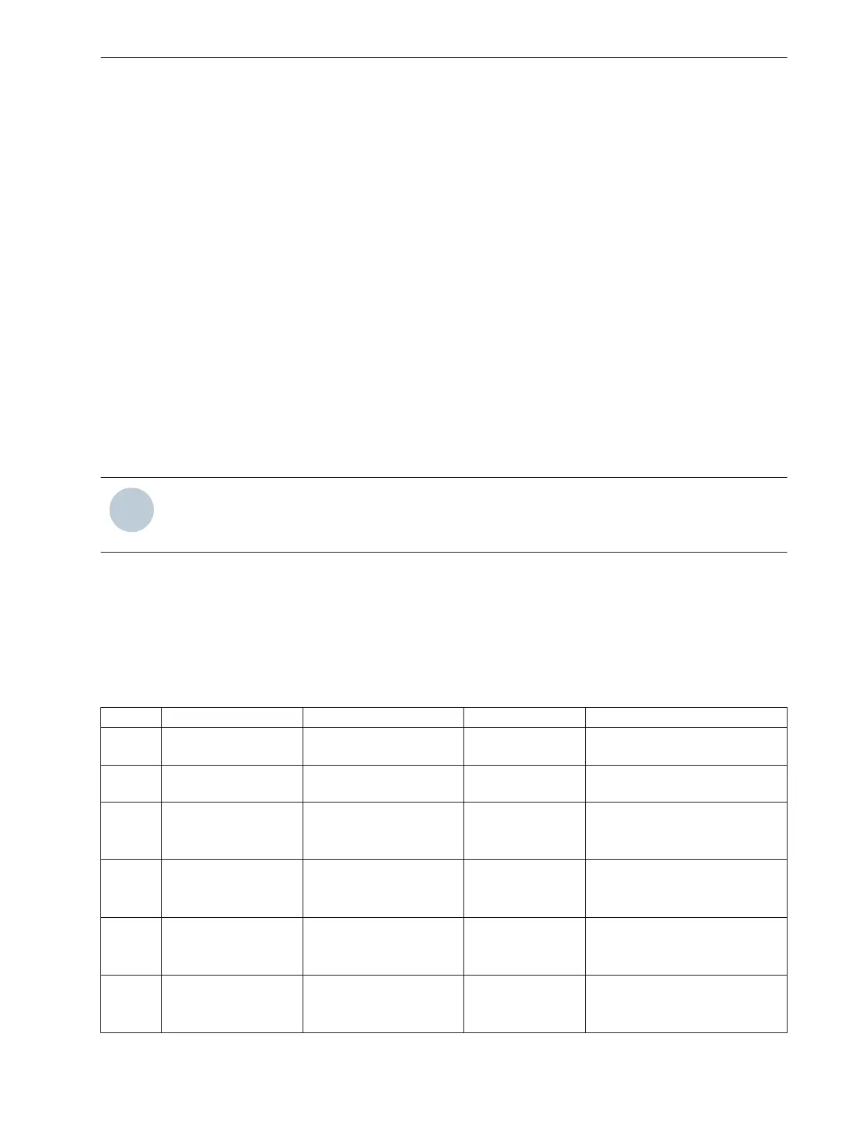
Settings
Addresses which have an appended “A” can only be changed with DIGSI, under “Additional Settings”.
Addr.
Parameter Setting Options Default Setting Comments
5901 FCT 81 O/U S2 OFF
ON
OFF 81 Over/Under Frequency Prot.
Side2
5902 Vmin S2 10 .. 150 V 65 V Min.required volt.for operation
Side2
5903 FCT 81-1 O/U S2 OFF
ON f>
ON f<
OFF 81-1 Over/Under Frequency Prot.
Side2
5904 FCT 81-2 O/U S2 OFF
ON f>
ON f<
OFF 81-2 Over/Under Frequency Prot.
Side2
5905 FCT 81-3 O/U S2 OFF
ON f>
ON f<
OFF 81-3 Over/Under Frequency Prot.
Side2
5906 FCT 81-4 O/U S2 OFF
ON f>
ON f<
OFF 81-4 Over/Under Frequency Prot.
Side2
2.30.3.3
Functions
2.30 Additional Applications with 6 Voltage Inputs
SIPROTEC Compact, 7SC80, Manual 441
E50417-G1140-C486-A8, Edition 07.2017