[7sc80-ct-supervision-131106, 1, en_US]
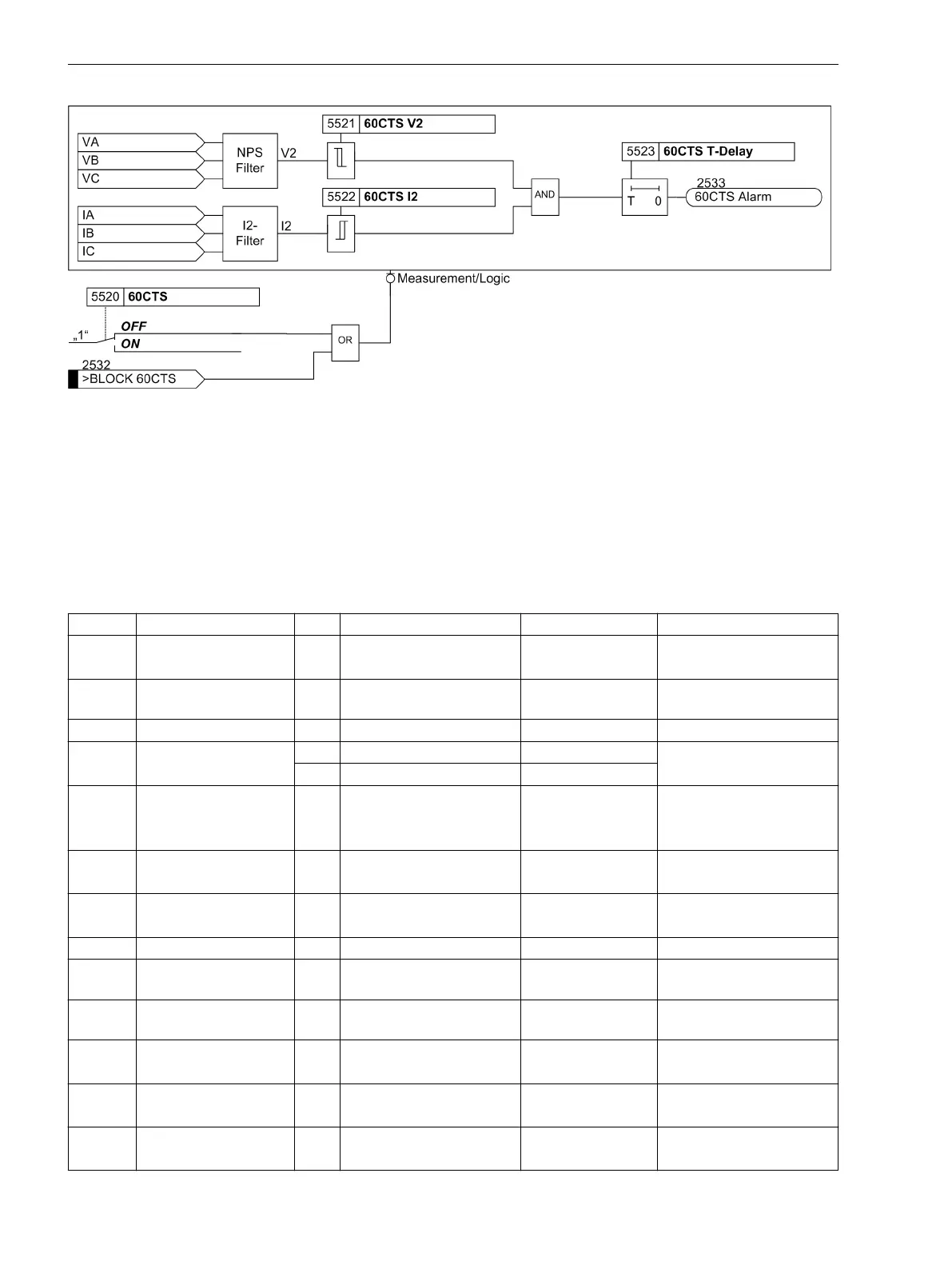
Figure 2-75 Current transformer monitoring
The voltage transformer monitoring and current transformer monitoring functions can only be used if the
measuring voltages Van, Vbn, Vcn or Vab, Vbc, VGnd are present at the device and parameter 213 VT
Connect. 3ph is set accordingly. If you have selected the wiring Vab, Vbc was selected, the monitoring
functions described above cannot be used.
Settings
The table indicates region-specific presettings. Column C (configuration) indicates the corresponding secon-
dary nominal current of the current transformer.
Addr.
Parameter C Setting Options Default Setting Comments
2201 INRUSH REST. OFF
ON
OFF Inrush Restraint
2202 2nd HARMONIC 10 .. 50 % 15 % 2nd. harmonic in % of
fundamental
2204 CROSS BLK TIMER 0.00 .. 180.00 sec 0.00 sec Cross Block Time
2205 I Max 1A 0.30 .. 25.00 A 7.50 A Maximum Current for
Inrush Restraint
5A 1.50 .. 125.00 A 37.50 A
2206 INRUSH DET. BY Phase
Cross
Sum
Phase Inrush detected by
5310 BLOCK PROT. NO
YES
YES Block protection by 60VTS
5501 46BC OFF
ON
OFF 46 Broken Conductor
5502 T 46BC 0.00 .. 100.00 sec 2.00 sec 46BC Delay Time
5503 Curr. Factor BC 0.00 .. 1.00 0.10 Current Factor for Broken
Conductor
5504 Volt. Factor BC 0.00 .. 1.00 0.10 Voltage Factor for Broken
Conductor
5505 CT Location Direction 1
Direction 2
Direction 1 Measurement location of
CT
5506 VT Location Direction 1
Direction 2
Direction 1 Measurement location of
VT
5510 60VTS OFF
ON with NPS
OFF 60VTS Voltage Transformer
Supervision
2.12.1.9
Functions
2.12 Monitoring Functions
240 SIPROTEC Compact, 7SC80, Manual
E50417-G1140-C486-A8, Edition 07.2017