Power System Data 2
Description
The general protection data (P.System Data 2) include parameters common to all functions, i.e. not asso-
ciated with a specific protection or monitoring function. In contrast to the P.System Data 1 discussed
before, they can be changed with the parameter group.
If the primary reference voltage and the primary reference current of the protected object are specified, the
device can calculate and issue the percentage operational measured values.
Setting Notes
Definition of Nominal Rated Values
At addresses 1101 FullScaleVolt. and 1102 FullScaleCurr., the primary reference voltage (phaseto-
phase) and reference current (phase) of the protected equipment is entered (e.g. motors). If these reference
sizes match the primary nominal values of the VTs and CTs, they correspond to the settings in address 202 and
204 (Section 2.1.3.2 Setting Notes). They are generally used to show values referenced to full scale.
Ground Impedance Ratios (only for Fault Location)
The adjustment of the ground impedance ratio is only important for the utilization of the line fault location
function. This is done by entering the resistance ratio RE/RL and the reactance ratio XE/XL.
The values under addresses 1103 and 1104 apply if only one line section is available and to all faults that
occur outside the defined line sections.
If several line sections are set, the following shall apply:
•
for line section 1, addresses 6001 and 6002
•
for line section 1, addresses 6011 and 6012
•
for line section 1, addresses 6021 and 6022.
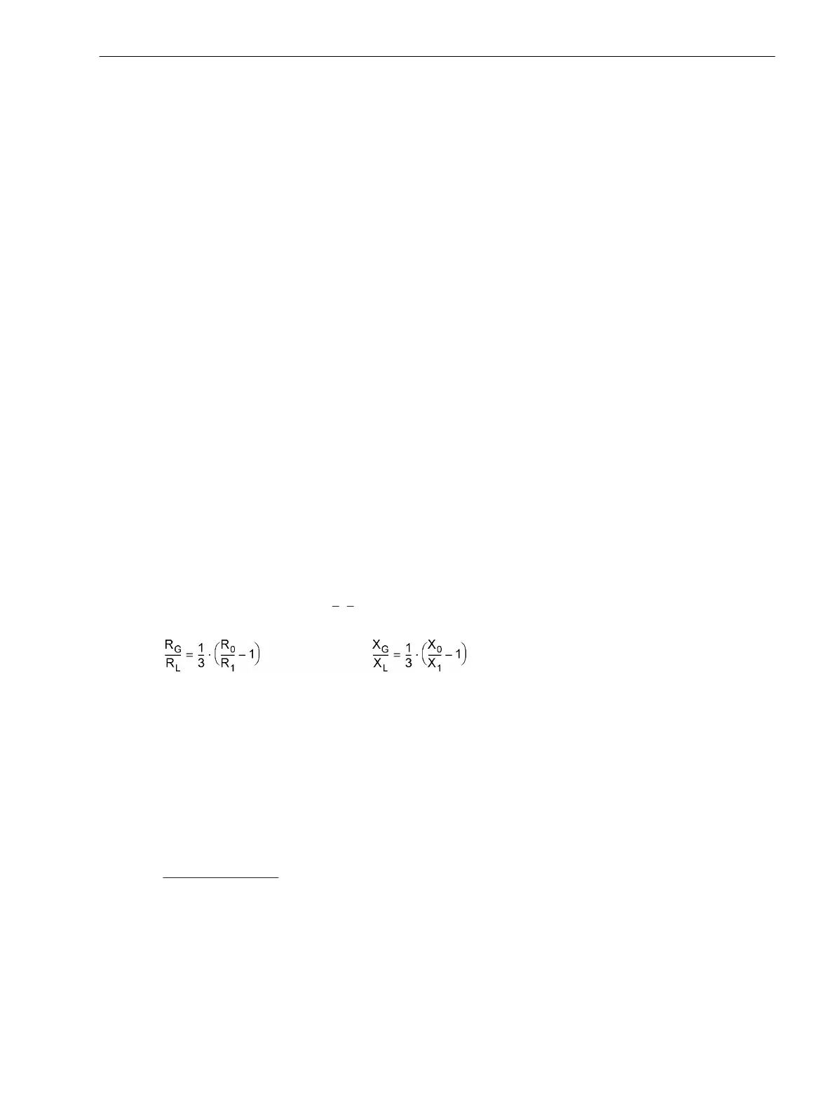
Resistance ratio RE/RL and reactance ratio XE/XL are calculated formally and do not correspond to the real
and imaginary components of
Z
E
/Z
L
. No complex calculation is required! The ratios can be obtained from the
line data using the following formulas:
[formelfehlerorter-260602-kn, 1, en_US]
Where
R
0
– Zero sequence resistance of the line
X
0
– Zero sequence reactance of the line
R
1
– Positive sequence resistance of the line
X
1
– Positive sequence reactance of the line
This data can be used for the entire line or line section, or as distance-related values, since the quotients are
independent of the distance.
Calculation example:
20 kV free line 120 mm
2
with the following data:
R
0
/s = 0.88 Ω/km (1.42 Ω/mile) Zero sequence resistance
X
0
/s = 1.26 Ω/km (2.03 Ω/mile) Zero sequence reactance
R
1
/s = 0.24 Ω/km (0.39 Ω/mile) Positive sequence resistance
X
1
/s = 0.34 Ω/km (0.55 Ω/mile) Positive sequence reactance
For ground impedance ratios, the following results:
2.1.6
2.1.6.1
2.1.6.2
Functions
2.1 General
SIPROTEC Compact, 7SC80, Manual 65
E50417-G1140-C486-A8, Edition 07.2017