[7sc80-erdfehler-u0-i0-messung-14012013, 1, en_US]
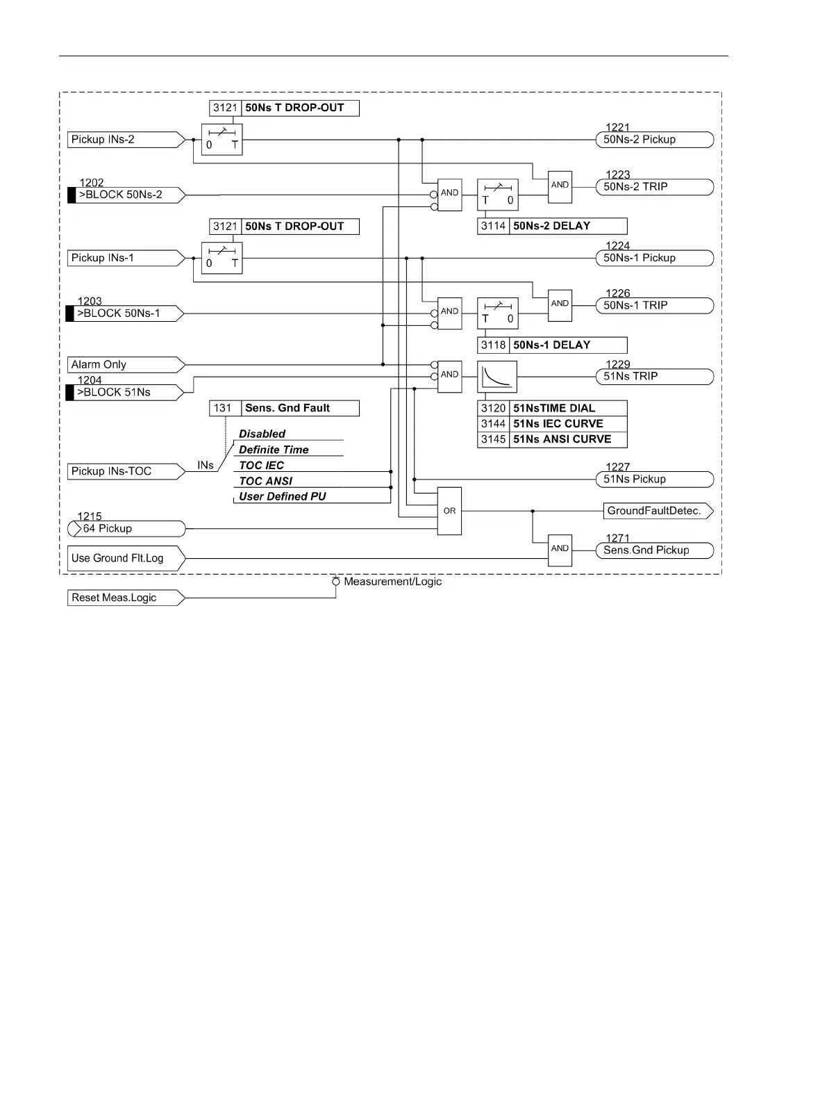
Figure 2-91
Logic Diagram for V0/Ι0 -φ Measurement, Part 2
Ground Fault Location
Application Example
Directional determination may often be used to locate ground faults. In radial systems, locating the ground
fault is relatively simple. Since all feeders from a common bus (Figure 2-92) deliver a capacitive charging
current, nearly the total ground fault current of the system is available at the measuring point of the faulty line
in the ungrounded system. In the resonant grounded system it is the residual wattmetric current of the
Petersen coil that flows via the measuring point. Therefore, on the faulty cables a clear "forward" decision is
made whereas in other feeders either "reverse" direction is sent back or no measurement is carried out in case
ground current is too low. Definitely the faulty line can be determined clearly.
2.13.3
Functions
2.13 Ground Fault Protection 64, 67N(s), 50N(s), 51N(s)
258 SIPROTEC Compact, 7SC80, Manual
E50417-G1140-C486-A8, Edition 07.2017