Process Terminal Connections
Fixing Elements
The process terminals feature integrated fixing elements. The head shape of the terminal screw allows for
using a simple flat screwdriver (4.0 x 0.8).
Stop Elements and Cable Cross-sections
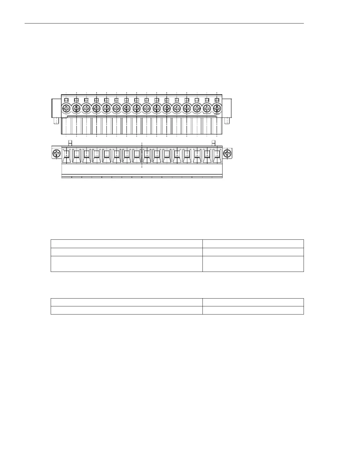
[7sc80-termial-180-110324, 1, --_--]
Figure 3-8 16-pin process terminal (cabinet surface mounting)
Use the suitable terminals, depending on the type of installation - cabinet flush mounting or cabinet surface
mounting. Compared to cabinet surface mounting, the terminal can be mounted rotated by 180° giving easier
access to the terminal screws. The ordering data is specified in the Appendix.
Solid conductors as well as stranded conductors with or without conductor sleeves can be used as single
cables. Siemens recommends using twin cable end sleeves when connecting two single cables.
Cable cross-sections:
AWG 18-12 (1.0 mm
2
to 2.5 mm
2
)
Permissible voltages: 300 V
Permissible currents: 5 A
Use copper conductors only!
Mechanical Requirements
The fixing elements and the connected components are designed for the following mechanical requirements:
Permissible tightening torque at the terminal screw
0.4 Nm to 0.5 Nm
Stripping length 7 mm
Interface Modules
General
The 7SC80 device is supplied with preconfigured interfaces in accordance with the MLFB. You do not have to
make any adaptations to the hardware (e.g. plugging in jumpers) yourself, except for the installation or
replacement of communication modules.
Replacing the Communication Module or GPS/IRIG-B Module
First, unscrew all screws with which the base is fixed to the device. Carefully remove the base.
Now unscrew the screws with which the communication module or GPS/IRIG-B module is fixed. Pay attention
to any plug connectors when removing the module.
3.1.2.3
3.1.2.4
Mounting and Commissioning
3.1 Mounting and Connections
460 SIPROTEC Compact, 7SC80, Manual
E50417-G1140-C486-A8, Edition 07.2017