[7sc80-synchro-fkt-querkuppl-24012013, 1, en_US]
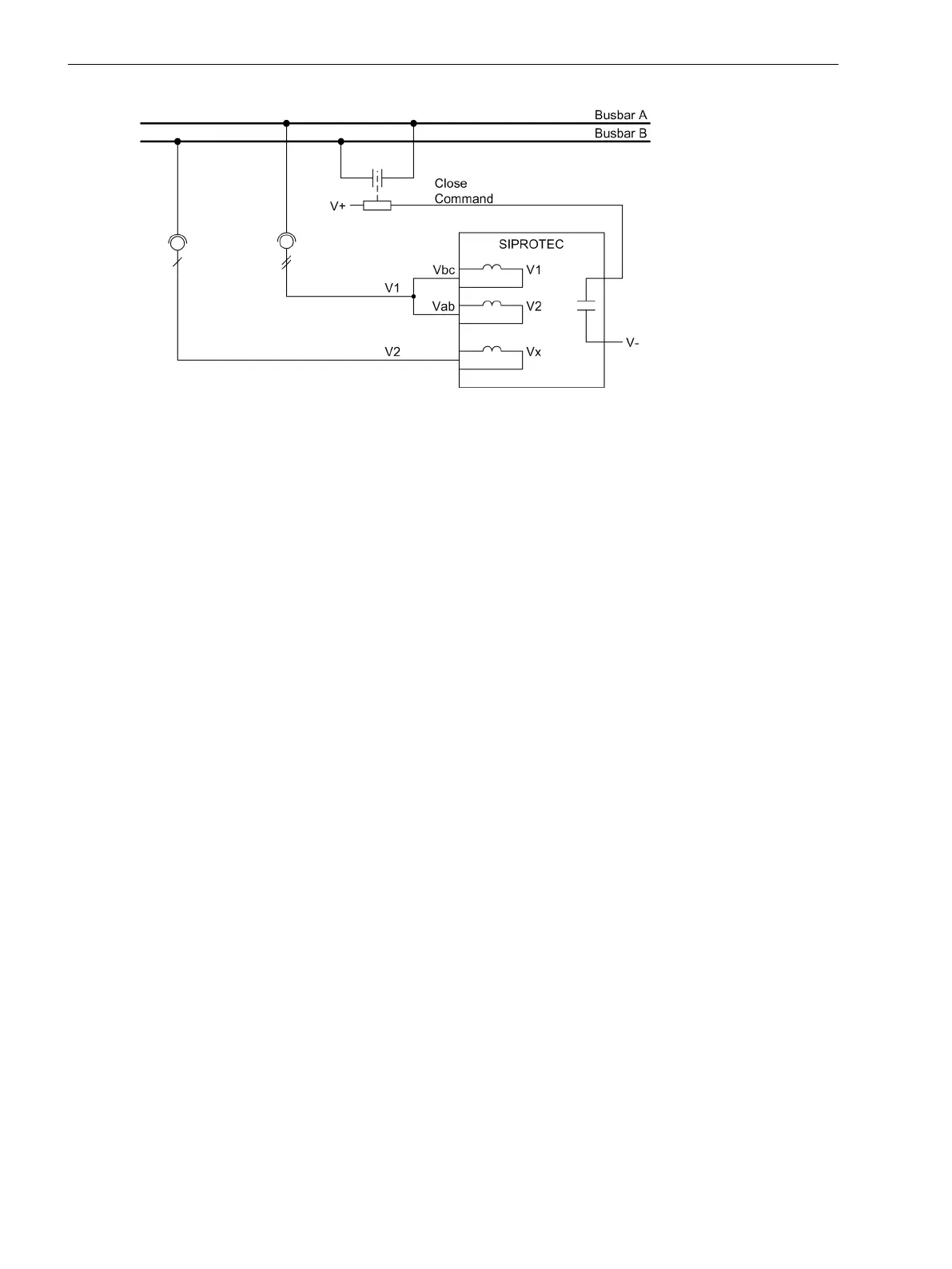
Figure 2-112 Busbar Coupling
The synchrocheck function of the 7SC80 usually coordinates with the integrated automatic reclosing system
and the control function. Nevertheless, it is also possible to employ an external automatic reclosing system. In
such a case, the signal exchange between the devices is to be accomplished via binary inputs and outputs.
The configuration determines whether the synchrocheck is to be carried out only in the case of automatic
reclosing or only in the case of circuit breaker control or in both cases. It is also possible to configure different
release criteria for automatic reclosing or control closing. Synchronous connection is always accomplished via
the integrated control.
The release command for closing under satisfied synchronism conditions can be deactivated via parameter
6113 25 Synchron. For special applications, the deactivated closing release can, however, be activated via a
binary input (
>25 synchr.
) (see “De-energized Switching”).
Connection
To compare the 2 voltages, the synchronization function uses the reference voltage V
1
and an additional
voltage V
2
that must be connected. You can use any phase-to-phase voltage or phase-to-ground voltage for
V
1
. For V
2
, use the voltage connected to V
x
. At address 6123, enter the connection type for V
2
.
Functional Sequence
Validity Check of the Configuration
Already during startup of the device, a validation check of the configuration is performed. If there is a fault,
the message
25 Set-Error
is output. after a measurement request there is a condition which is not plau-
sible, the message
25 Sync. Error
is output. The measurement is then not started.
When setting the parameters, make sure that address 6106 (threshold V1, V energized) is smaller than
address 6103 (lower voltage limit Vmin). The synchronization function cannot be controlled via a binary input.
SYNC Error
The synchronization is not started if a voltage transformer failure (m.c.b. tripping) is communicated to the
device via the binary input 6509
>FAIL:FEEDER VT
or 6510
>FAIL: BUS VT
. The message
25 Sync.
Error
is output. In this case, the synchronization can be controlled directly via a binary input.
In case of a protection pickup, the complete synchronization process is reset instantaneously.
Release
The synchrocheck function only operates if it receives a measurement request. This request may be issued by
the internal control function, the automatic reclosing function or externally via a binary input, e.g. from an
external automatic reclosing system.
2.20.2
Functions
2.20 Synchrocheck
338 SIPROTEC Compact, 7SC80, Manual
E50417-G1140-C486-A8, Edition 07.2017