[handein-260602-kn, 1, en_US]
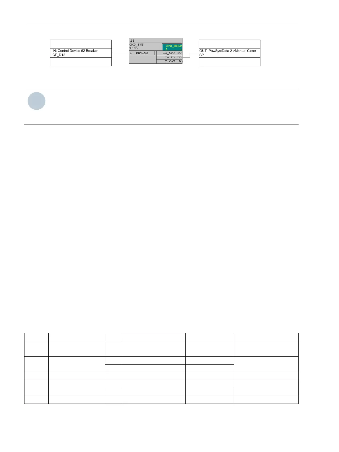
Figure 2-37 Example for the generation of a manual close signal using the internal control function
NOTE
For an interaction between the automatic reclosing function (79 AR) and the control function, an extended
CFC logic is necessary. See margin heading “Close command: Directly or via Control” in the Setting Notes of
the automatic reclosing function (Section 2.14.6 Setting Notes).
Interaction with Automatic Reclosure Function (phases)
If reclosing occurs, it is desirable to have high-speed protection against faults with 67-2. If the fault still exists
after the first reclosure, the elements 67-1 or 67-TOC are started with graded tripping times, causing the 67-2
elements to be blocked. Parameter 1514 67-2 active can be used to specify whether the 67-2 elements are
influenced by a release signal of the internal or an external automatic reclosing device or not. The setting
with 79 active determines that the 67-2 elements are only released if the automatic reclosing function is
not blocked. If this is not desired, the setting always is selected so that the 67-2 elements are always active.
The integrated automatic reclosing function of 7SC80 also provides the option to determine individually for
each overcurrent element whether tripping or blocking is to be carried out instantaneously, unaffected by the
AR with time delay (see Section 2.14 Automatic Reclosing System 79).
Interaction with Automatic Reclosing Function (ground)
If reclosing occurs, it is desirable to have high-speed protection against faults with 67N-2. If the fault still exists
after the first reclosure, the elements 67N-1 or 67N-TOC are started with graded tripping times, causing the
67N- 2 elements to be blocked. Parameter 1614 67N-2 active can be used to specify whether the 67N-2
elements are influenced by a release signal of the internal or external automatic reclosing device or not. The
setting with 79 active determines that the 67N-2 elements are only released if the automatic reclosing
function is not blocked. If this is not desired, the setting always is selected so that the 67N-2 elements are
always active.
The integrated automatic reclosing function of 7SC80 also provides the option to determine individually for
each overcurrent element whether tripping or blocking is to be carried out instantaneously, unaffected by the
AR with time delay (see Section 2.14 Automatic Reclosing System 79).
Settings
Addresses which have an appended “A” can only be changed with DIGSI, under “Additional Settings”.
The table indicates region-specific presettings. Column C (configuration) indicates the corresponding secon-
dary nominal current of the current transformer.
Addr.
Parameter C Setting Options Default Setting Comments
1501 FCT 67/67-TOC OFF
ON
OFF 67, 67-TOC Phase Time
Overcurrent
1502 67-2 PICKUP 1A 0.10 .. 30.00 A; ∞ 2.00 A 67-2 Pickup
5A 0.50 .. 150.00 A; ∞ 10.00 A
1503 67-2 DELAY 0.00 .. 7200.00 sec; ∞ 0.10 sec 67-2 Time Delay
1504 67-1 PICKUP 1A 0.10 .. 30.00 A; ∞ 1.00 A 67-1 Pickup
5A 0.50 .. 150.00 A; ∞ 5.00 A
1505 67-1 DELAY 0.00 .. 7200.00 sec; ∞ 0.50 sec 67-1Time Delay
2.3.11
Functions
2.3 Directional Overcurrent Protection 67, 67N
134 SIPROTEC Compact, 7SC80, Manual
E50417-G1140-C486-A8, Edition 07.2017