Transformers and cable are prone to damage by overloads that last for an extended period of time. Overloads
cannot and should not be detected by fault protection. Time overcurrent protection should be set high
enough to only detect faults since these must be cleared in a short time. Short time delays, however, do
neither allow measures to discharge overloaded equipment nor do they permit to take advantage of its
(limited) overload capacity.
The 7SC80 devices feature an overload protection function with thermal tripping characteristic adaptable to
the overload capability of the equipment being protected (overload protection with memory function).
Overload protection can be switched ON or OFF or set to Alarm Only at address 4201 FCT 49. If overload
protection is ON, tripping, trip log and fault recording is possible.
When setting Alarm Only no trip command is given, no trip log is initiated and no spontaneous fault annun-
ciation is shown on the display.
NOTE
Changing the function parameters resets the thermal replica. The thermal model is frozen (kept constant),
as soon as the current exceeds the setting value 1107 I MOTOR START.
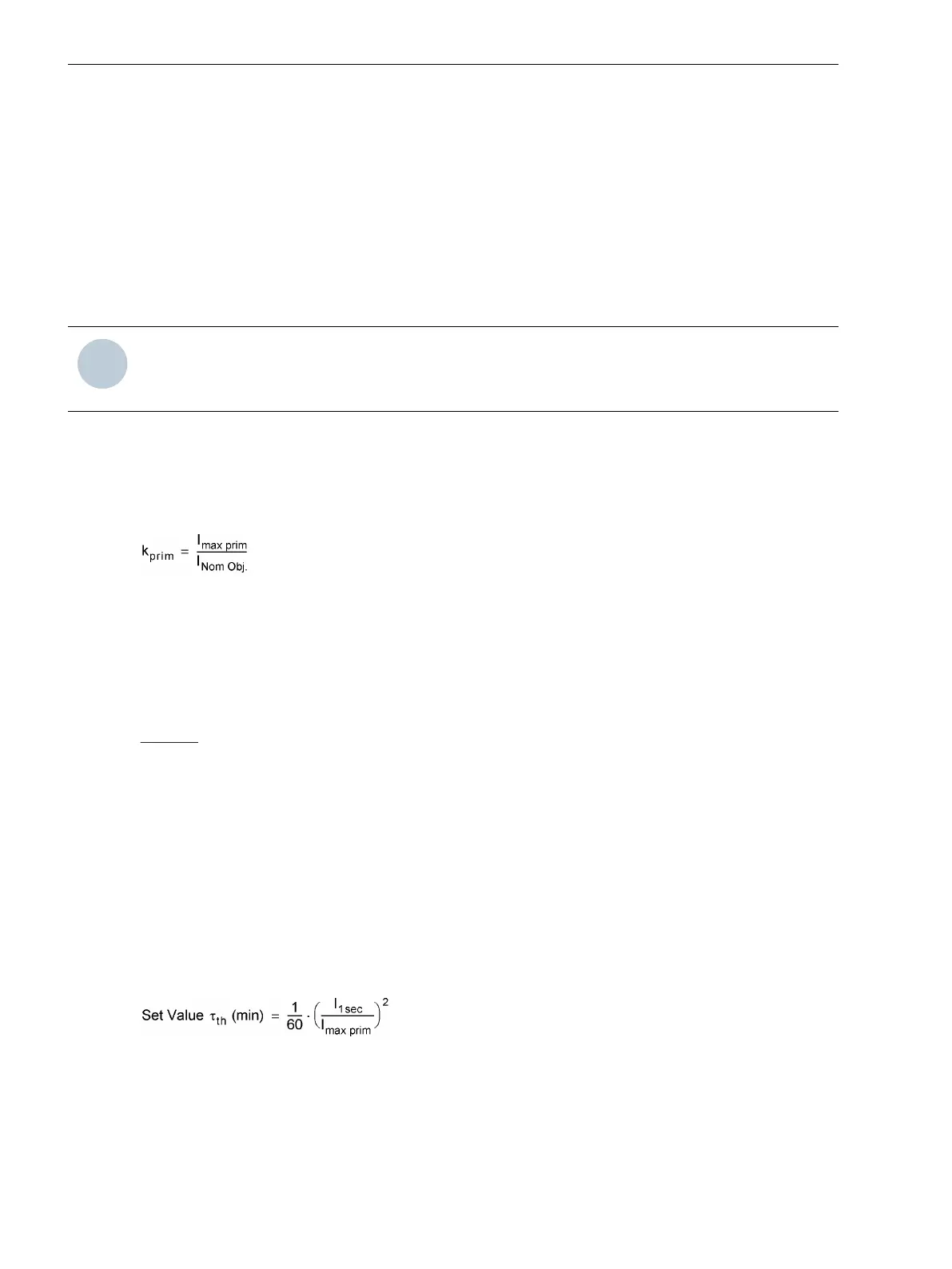
Overload Parameter k-factor
The overload protection is set in reference values. The nominal current Ι
Nom Obj.
of the protected object (trans-
former, cable) is used as the basic current for overload detection. By means of the thermally permanently
permissible current Ι
max
, a factor k
prim
can be calculated:
[formel-kfaktor-260602-kn, 1, en_US]
The thermally permissible continuous current for the equipment being protected can generally be concluded
from manufacturers' specifications. For cables, the permissible continuous current depends, among other
factors, on the cross-section, insulating material, design, and the cable routing. It is specified in the pertinent
tables or by the cable manufacturer. If no specifications are available, select 1.1 times the nominal current.
There are usually no specifications for overhead lines, but we can also assume an admissible overload of 10 %
here.
Example: Belted cable 10 kV, 150 mm
2
:
Permissible continuous current
Ι
max
= 322 A
Nominal current with k-factor 1.1
Ι
Nom Obj.
= 293 A
Time Constant
The overload protection tracks overtemperature progression, employing a thermal differential equation whose
steady state solution is an exponential function. The TIME CONSTANT τ
th
(set at address v) is used in the
calculation to determine the threshold of overtemperature and thus, the tripping temperature.
For cable protection, the heat-gain time constant τ is determined by cable specifications and by the cable envi-
ronment. If no time-constant specification is available, it may be determined from the short-term load capa-
bility of the cable. The 1-sec current, i.e. the maximum current permissible for a one-second period of time, is
often known or available from tables. Then, the time constant may be calculated with the formula:
[einstellwert-tau-260602-kn, 1, en_US]
If the short-term load capability is given for an interval other than one second, the corresponding short-term
current is used in the above formula instead of the 1-second current, and the result is multiplied by the given
duration. For example, if the 0.5-second current rating is known:
Functions
2.11 Thermal Overload Protection 49
222 SIPROTEC Compact, 7SC80, Manual
E50417-G1140-C486-A8, Edition 07.2017