[ausloesekennl-260602-kn, 1, en_US]
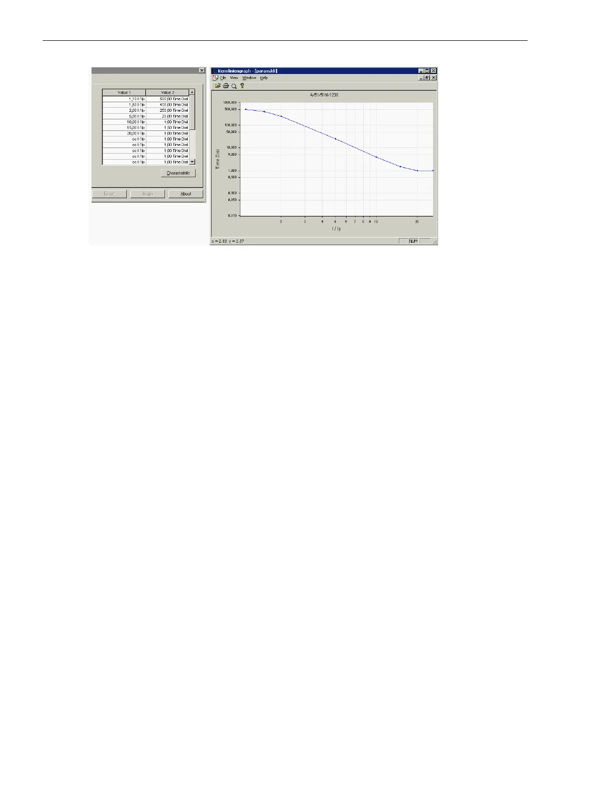
Figure 2-20 Entry and visualization of a user-defined tripping characteristic in DIGSI — example
Die Auslösezeit können Sie durch eine parametrierbare, konstante Zeit verlängern. Die Einstellung für die
Überstromstufe Ιp erfolgt mit Hilfe des Parameters 1225 51 Time adder and für die Überstromstufe ΙEp
durch Parameter 1325 51N Time adder.
Inrush Restraint
When using the protection device at transformers with large inrush currents, the inrush current detection can
be activated in the 7SC80.
The general setting notes for the inrush current detection are described in Section 2.12.1.8 Setting Notes.
The inrush current detection can be enabled and disabled in elements at addresses:
50-3 element
Address 2207 50-1 w. Inrush
50-2 element Address 2208 50-2 w. Inrush
50-1 element Address 2209 50-3 w. Inrush
51 element Address 2210 51 w. Inrush
51-1 element Address 2221 51-1 w. Inrush
51-2 element Address 2222 51-2 w. Inrush
51-3 element Address 2223 51-3 w. Inrush
51-4 element Address 2224 51-4 w. Inrush
50N-3 element Address 2211 50N-1 w. Inrush
50N-2 element Address 2212 50N-2 w. Inrush
50N-1 element Address 2213 50N-3 w. Inrush
51N element Address 2214 51N w. Inrush
51N-1 element Address 2226 51N-1 w. Inrush
51N-2 element Address 2227 51N-2 w. Inrush
51N-3 element Address 2228 51N-3 w. Inrush
51N-4 element Address 2229 51N-4 w. Inrush
Manual Close Mode (phases ground)
When a circuit breaker is closed onto a faulted line, a high-speed trip by the circuit breaker is usually desired.
For overcurrent or high-set element the delay may be bypassed via a Manual Close pulse, thus resulting in
instantaneous tripping. The internal "Manual close" signal is built from the binary input signal >Manual Close
(no.
356
). The internal "Manual close" signal remains active as long as the binary input signal >Manual Close is
active, but at least for 300 ms (see the following logic diagram). To enable the device to react properly on
occurrence of a fault in the phase element, address 1213 MANUAL CLOSE has to be set accordingly. Corre-
spondingly, address 1313 MANUAL CLOSE is considered for the ground path address. Thus, the user deter-
Functions
2.2 Overcurrent Protection 50, 51, 50N, 51N
94 SIPROTEC Compact, 7SC80, Manual
E50417-G1140-C486-A8, Edition 07.2017
 Loading...


