1PosInc/Analog
4.6 Functions of the 1PosInc/Analog
ET 200S Positioning
144 Operating Instructions, 05/2007, A5E00124871-04
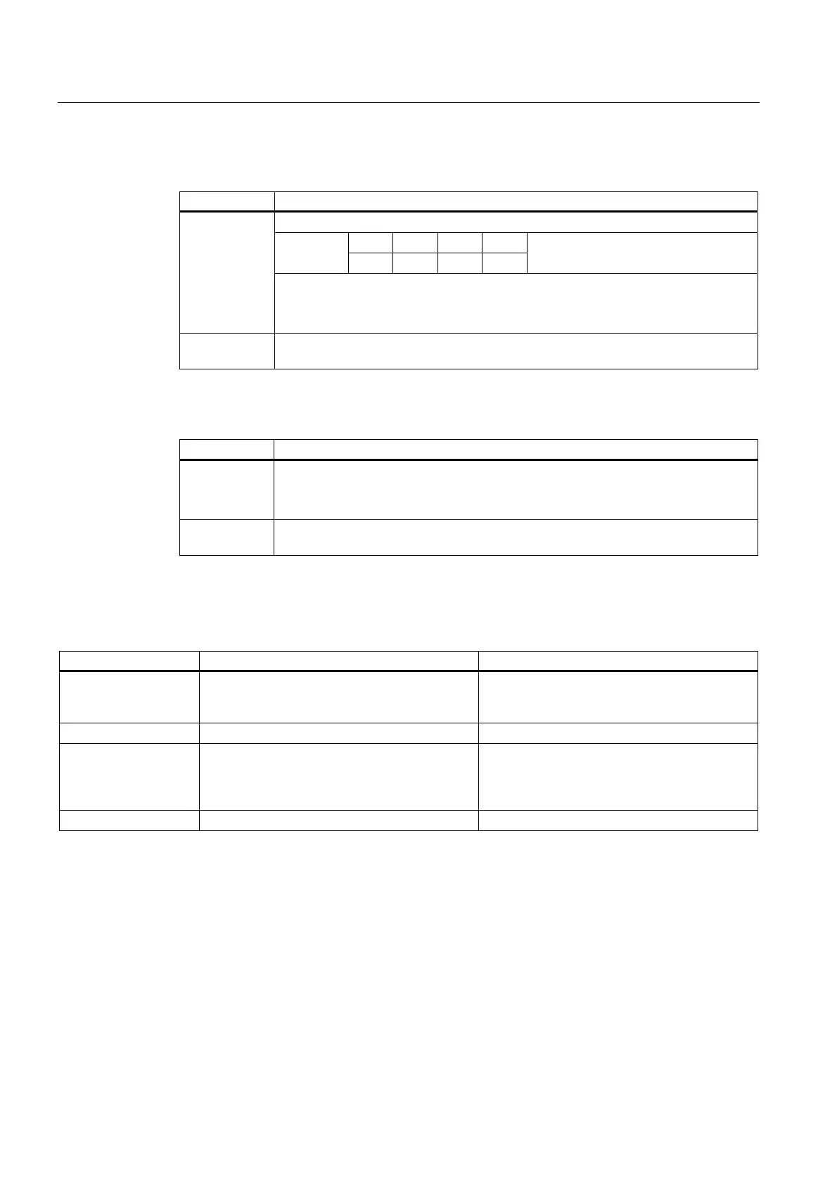
Control Signals: Inching
Address Assignment
Bits 0.7 to 0.4:
7 6 5 4 Bit
0 0 0 1
MODE 1 = Inching
Byte 0
Bit 2: DIR_M
Bit 1: DIR_P
Bit 0: START
Bytes 1 to 3 Voltage for inching
(0 to 32 511)
Feedback Signals: Inching
Address Assignment
Byte 0 Bit 2: POS_ DONE
Bit 1: POS_ERR
Bit 0: POS_ACK
Bytes 1 to 3 Actual value
(linear axis: 0 to 16 777 215; rotary axis: 0 to end of rotary axis - 1)
Inching: Causes of Errors for POS_ERR
You must find out the causes of errors with JOB 15 (displays current values).
Error Number Cause What to Do
5 The limit switch that lies in the direction in which
the drive is moved is active
Check your switches and the wiring as well as
the DI0 limit switch minus and DI1 limit switch
plus parameters
7 Inching: DIR_P and DIR_M = 1
13 Direction of rotation of the drive and the
encoder varies
Check the wiring of the drive and the encoder
as well as the parameter for the reversal of the
direction of rotation and adapting the direction
of the drive.
Voltage for inching >32 511 or < 0

 Loading...


