1PosInc/Analog
4.9 Control and Feedback Signals
ET 200S Positioning
Operating Instructions, 05/2007, A5E00124871-04
181
4.9 Control and Feedback Signals
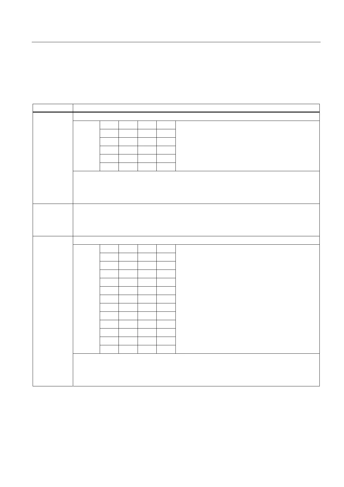
Assignment of the Control Interface
Address Assignment
Bits 0.7 to 0.4 stand for the MODEs
7 6 5 4
0 0 0 0
0 0 0 1
0 0 1 1
0 1 0 0
Bit
0 1 0 1
MODE 0 = Stop
MODE 1 = Inching
MODE 3 = Reference Point Run
MODE 4 = Relative Positioning
MODE 5 = Absolute Positioning
Byte 0
Bit 3: CTRL_DO
Bit 2: DIR_M
Bit 1: DIR_P
Bit 0: START
Bytes 1 to 3 In MODE 1= inching: voltage for inching
With MODE 3 = reference point run: reference point coordinates
at MODE 4 = Relative positioning: distance
at MODE 5 = Absolute positioning: target
Bits 4.7 to 4.4 stand for the MODEs
7 6 5 4
0 0 0 0
0 0 0 1
0 0 1 1
0 1 0 0
0 1 0 1
0 1 1 0
0 1 1 1
1 0 0 0
1 0 0 1
1 0 1 0
1 0 1 1
Bit
1 1 1 1
JOB 0 = Cancel JOB processing
JOB 1 = Set the actual value
JOB 3 = Change the switch-off difference
JOB 4 = Change the switchover difference
JOB 5 = Change the voltage for rapid feed
JOB 6 = Change the voltage for creep feed
JOB 7 = Changing the acceleration T
acc
JOB 8 = Changing the Deceleration T
dec
JOB 9 = Evaluate the reference signal
JOB 10 = Latch function
JOB 11 = Set the monitoring of the direction of rotation
JOB 15 = Display current values
Byte 4
Bit 3: EXTF_ACK
Bit 2:Reserve = 0
Bit 1: Reserve = 0
Bit 0: JOB_REQ

 Loading...


