1PosSSI/Digital
5.9 Control and Feedback Signals
ET 200S Positioning
236 Operating Instructions, 05/2007, A5E00124871-04
5.9 Control and Feedback Signals
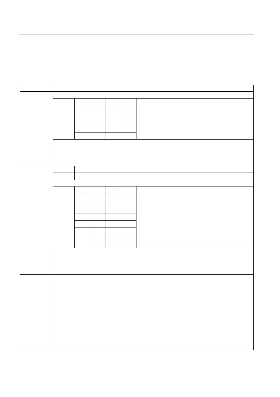
Assignment of the Control Interface
Address Assignment
Bits 0.7 to 0.4 stand for the MODEs
7 6 5 4
0 0 0 0
0 0 0 1
0 0 1 1
0 1 0 0
Bit
0 1 0 1
MODE 0 = Stop
MODE 1 = Inching
MODE 3 = Reference Point Run
MODE 4 = Relative Positioning
MODE 5 = Absolute Positioning
Byte 0
Bit 3: SPEED (SPEED = 0 is creep feed; SPEED = 1 is rapid feed)
Bit 2: DIR_M
Bit 1: DIR_P
Bit 0: START
at MODE 4 = Relative positioning: distance Bytes 1 to 3
at MODE 5 = Absolute positioning: target
Bits 4.7 to 4.4 stand for the MODEs
7 6 5 4
0 0 0 0
0 0 0 1
0 0 1 0
0 0 1 1
0 1 0 0
1 0 1 0
1 0 1 1
Bit
1 1 1 1
JOB 0 = Cancel JOB processing
JOB 1 = Set the actual value
JOB 2 = Move encoder range
JOB 3 = Change the switch-off difference
JOB 4 = Change the switchover difference
JOB 10 = Latch function
JOB 11 = Set the monitoring of the direction of rotation
JOB 15 = Display current values
Byte 4
Bit 3: EXTF_ACK
Bit 2:Reserve = 0
Bit 1: Reserve = 0
Bit 0: JOB_REQ
Bytes 5 to 7 Corresponding to the selected JOB:
• With JOB 1= actual value coordinates
• With JOB 3 = switch-off difference
• With JOB 4 = switchover difference
• With JOB 10
– Byte 5: Bit 0 = latch at positive edge at DI2
– Byte 5: Bit 1 = latch at negative edge at DI2
• With JOB 11 = path difference for direction of rotation monitoring
• With JOB 15
– Byte 5: 0 = Residual distance
– Byte 5: 1 = Actual speed
– Byte 5: 2 = error information

 Loading...


